153
b
Press Section
chap.4
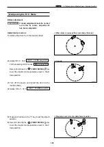
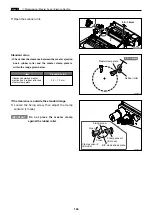
20mm
Rear end of opening
Press roll
Main motor shaft
Drum flange
Mark
Press roll
Adjust collar
Hex bolts
Make
mark here
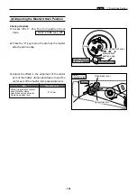
(2) Adjusting the Printing Area (Press OFF Timing)
¡
For description of operation.
Adjustment procedure
1.
Make a mark on the end surface of the drum
flange, in a position
20mm
forward (in the direc-
tion of the forward end) from the rear end of the
drum's opening(hole section).
2.
With the press roll activated, turn the main
motor shaft by hand, and stop turning when the
press roll starts to descend (move in the direction
of the arrow).
Standard value
¡
Open the front cover, and check whether the
center of the press roll is aligned with the
mark made in step
1
.
NOTE :
Standard value
Item
Alignment of mark on flange
end and center of press roll
±
2 mm
If the alignment is not correct:
1.
Loosen the 2 hex bolts indicated.
2.
Loosen the adjustment collar (eccentric) fixing
screw.
3.
Turn the adjustment collar (eccentric) to move
the flange and adjust the alignment.
Moving the flange upward makes turning off of
the press occur later
\
thereby making the
printing range longer
Moving the flange downward makes turning off
of the press occur earlier
\
thereby making the
printing range shorter
\
See page 74
R8S04033
R8S04034
R8S04035
R8S04032
Hex bolts
Fixing screw
Summary of Contents for DP-S Series
Page 1: ......
Page 9: ......
Page 11: ......
Page 16: ...x Dimensions chap 1 15 R8S01001 xDimensions 622 1360 510 228 1080 710 980 688 370 mm...
Page 22: ...v Part Names and Their Functions chap 1 21 44000A1e 2A 2B 2C R8S01006a 2Detailed drawing...
Page 33: ...32 z Scanner Section chap 2 Circuit R8S02E03e...
Page 87: ...86 m Drum Section chap 2 2 Circuit R8S02E30...
Page 171: ...170 MEMO...
Page 193: ...192 MEMO...
Page 195: ...194 z Help mode List chap 7 z HELP Mode List...
Page 243: ...242 c HELP Mode Function and Operation Procedures chap 7...
Page 270: ...269 c HELP Mode Function and Operation Procedures chap 7...
Page 281: ...280 MEMO...
Page 293: ...292 z Electrical Parts Layout and Their Functions chap 9 MEMO...
Page 295: ...309 294 x Overall Wiring Layout chap 9 Overall Wiring Layout 1 Main PCB 2 2...
Page 297: ...311 296 x Overall Wiring Layout chap 9 Overall Wiring Layout 2 Drive PCB 2 2...

