background image

 TM 

95263 

00 


TECHNICAL MANUAL 


OPERATOR AND FIELD MAINTENANCE MANUAL 


FOR


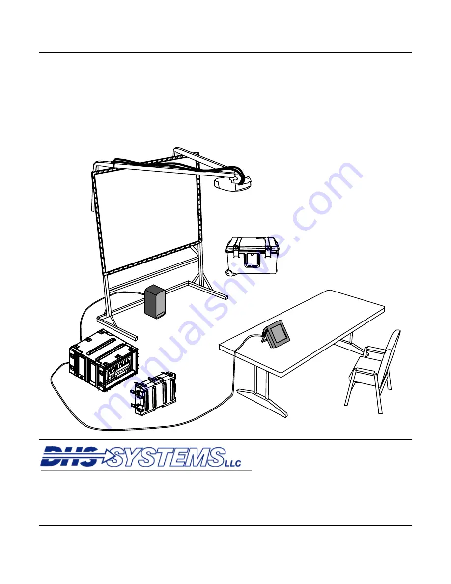
Audio-Visual Component System (AVCS) 


33 Kings Highway

Orangeburg, NY 10962


Phone

:     845-359-6066 


Fax

:         845-365-2114 


Hotline

:    800-977-3647 

DHS MANUAL PART NUMBER 95263 00 


Web

www.drash.com


E

mail:  [email protected]


18 SEP 2008 

  ISO 9001:   2000 Registered   
 Quality Management System 

Summary of Contents for TM 95263 00

Page 1: ...FOR Audio Visual Component System AVCS 33 Kings Highway Orangeburg NY 10962 Phone 845 359 6066 Fax 845 365 2114 Hotline 800 977 3647 DHS MANUAL PART NUMBER 95263 00 Web www drash com Email drash drash...

Page 2: ......

Page 3: ...OSSIBLE DO NOT TRY TO PULL OR GRAB THE INDIVIDUAL IF POSSIBLE TURN OFF THE ELECTRICAL POWER IF YOU CANNOT TURN OFF THE ELECTRICAL POWER PULL PUSH OR LIFT THE PERSON TO SAFETY USING A DRY WOODEN POLE O...

Page 4: ...ous areas When possible shut off power supply to equipment before beginning work on equipment Take particular care to ground every capacitor that could potentially store a dangerous electrical charge...

Page 5: ...ave been disconnected and generator has been shut down AVOID THE POWER INPUT Be careful not to contact 115 VAC input connections when installing or servicing equipment DO NOT SERVICE ALONE Never work...

Page 6: ...s injury or death Refer to the following weight limits as guidelines Handling Function One Person Max Lift Two Person Max Lift Two Person Max Lift Male Only Lift object from floor and place it on surf...

Page 7: ...performing maintenance on this equipment Secure all loose fitting clothing to prevent from being caught in moving or rotating parts Death or loss of limb may result WARNING Do not attempt to service...

Page 8: ......

Page 9: ...EMBER 2008 TOTAL NUMBER OF PAGES FOR FRONT AND REAR MATTER IS 135 AND TOTAL NUMBER OF WORK PACKAGES IS 59 CONSISTING OF THE FOLLOWING Page WP No Change No Page WP No Change No Cover 1 0 Chp 5 title pa...

Page 10: ......

Page 11: ...2 Theory of Operation 0003 CHAPTER 2 OPERATOR INSTRUCTIONS Description and Use of Controls Indicators and Connectors 0004 Setup Procedures 0005 Operation Under Usual Conditions 0006 Operation Under Un...

Page 12: ...cerning the equipment Theory of Operation appropriate to the maintenance level covered is also provided Chapter 2 Operator Instructions This chapter provides a description and location of the controls...

Page 13: ...n using the Table of Contents in the manual s front matter and using the Index in the manual s rear matter Locating a WP in the Table of Contents First determine the category of the WP subject and the...

Page 14: ...TION AVCS EQUIPMENT DESCRIPTION AND DATA On the second and subsequent pages of the WP the manual and WP number is repeated The page number is placed at the bottom of the page and consists of the WP nu...

Page 15: ...DHS Systems LLC TM 95236 00 CHAPTER 1 GENERAL INFORMATION EQUIPMENT DESCRIPTION AND THEORY OF OPERATION FOR AVCS MINI...

Page 16: ......

Page 17: ...o support the modern Command Post CP This system and its supporting components allows the commander and staff to view the Common Operational Picture COP directly monitor various feeds and display addi...

Page 18: ...s know Submit an EIR You the user are the only one who can tell us what you don t like about your equipment Let us know why you don t like the design or performance Put it on an SF 368 Product Quality...

Page 19: ...administrative storage If inside storage is not available use trucks vans or other containers WARRANTY INFORMATION The AVCS has a limited 1 year warranty with the following exceptions Deployable Comma...

Page 20: ...es HDBK Handbook HMMWV High Mobility Multi Purpose Wheeled Vehicle HVAC Heating Ventilating and Air Conditioning I O Input Output LED Light Emitting Diode MAC Maintenance Allocation Chart MOS Military...

Page 21: ...which can cause damage to equipment or loss of mission 2 Recognize equipment may require at least a two person carry Follow number of lifter requirements in safety marking labels or stencils and cauti...

Page 22: ......

Page 23: ...nt display windows The audio mixer will accept up to two microphone level inputs and two line level inputs providing two line level audio outputs with one designated as a speaker output for the suppli...

Page 24: ...access to the display screens for the control processor Figure 2 Item 1 audio mixer Figure 2 Item 2 and window processor Figure 2 Item 3 The DC2E Mini System is designed to operate while the front AV...

Page 25: ...onnection one quick disconnect to attach the touch panel cable one serial connection for use with an external device and one Internet Protocol IP Reset button which resets the IP address of the system...

Page 26: ...eyed except as indicated in the legend on the cover of this document ANCILLARY EQUIPMENT TRANSPORT CASE The Ancillary Equipment Transport Case Figure 4 transports one touch panel one audio speaker and...

Page 27: ...t 40 4 L x 27 W x 16 6 H 103 cm L x 69 cm W x 42 cm H Weight 115 lbs 52 kg Input Operating Voltage 120VAC Power Consumption system only 6 amps 72 watts 120v AC Operating Temperature average 41 F 113 F...

Page 28: ......

Page 29: ...eeds and composite sources into video windows on a single display device Video is output using two mirrored analog HD15 connectors CONTROL PROCESSOR The control processor provides unified control of t...

Page 30: ......

Page 31: ...DHS Systems LLC TM 95236 00 CHAPTER 2 OPERATOR INSTRUCTIONS FOR AVCS MINI...

Page 32: ......

Page 33: ...n the transit cases Tables identify the callout numbers item name based on panel markings and functional description AVCS FRONT CP E 2 CONTROL PROCESSOR PW R NET CRESTON LAN HW R SW R MSG LNK ACT Alar...

Page 34: ...sor Front Table 2 Control Processor Front Controls Indicators and Connectors ITEM CONTROLS INDICATORS AND CONNECTORS FUNCTION 1 PWR Indicator Light Green Indicates power to the unit 2 NET Indicator Li...

Page 35: ...CTORS FUNCTION 1 Display Displays service contact phone number and menu items 2 DOWN Button Scrolls backward through menu items 3 UP Button Scrolls forward through menu items 4 ENTER Button Selects me...

Page 36: ...w Processor Front Table 4 Window Processor Front Controls Indicators and Connectors ITEM CONTROLS INDICATORS AND CONNECTORS FUNCTION 1 ALARM Indicator Light Amber Indicates system error or internal el...

Page 37: ...N T L INE O K isobar LINE 1 LINE 2 MIC 2 MIC 1 1 2 3 4 5 6 Figure 5 AVCS Rear Panel Controls Indicators and Connectors Table 5 AVCS Rear Panel Controls Indicators and Connectors ITEM CONTROLS INDICATO...

Page 38: ...LINE PR O T EC TI O N LI NEA SPEAKER A UDIO OUT C ON TROL V ID EOIN AU DIOIN W E IG HTR A NG E 80 10 0LBS H ARDIG G FA U LT P R ESENT LI N E O K isoba r LINE 1 LINE 2 MIC 2 MIC 1 1 2 PRO TECT IO N F...

Page 39: ...UCH PANEL POTS LINE PROTECTI O N LI NEA SPEAKER AU DIOOUT CON TR OL V IDE OIN AUD IOIN W EIGH TR AN GE 8 0 100L BS HA RD I GG FAULT PRESEN T LI NE OK isobar LINE 1 LINE 2 MIC 2 MIC 1 1 MIC 1 LINE 1 AU...

Page 40: ...NEL PO TS LINE PRO TEC TI O N LINEA SPEAKER A UDIO OU T CONTROL V ID E OIN A UDIO IN W E IGH TRA N GE 80 10 0LB S H AR DI G G FAU L T PRE SENT LI NE O K is obar LI NE 1 LINE 2 MI C 2 MI C 1 1 LINE A S...

Page 41: ...INE 2 MIC 2 MIC 1 EXTERNAL DEVICE CTL IP RESET CTL LAN TOUCH PANEL POTS LINE CONTROL 2 3 5 4 1 Figure 9 AVCS Rear Control Panel Table 9 AVCS Rear Controls Indicators and Connectors ITEM CONTROLS INDIC...

Page 42: ...A SPEAKER AUD IOOU T CONTROL V ID E OIN A UDIO IN WE IGH TRA N GE 80 1 00LB S H AR DI G G FAULT PRES ENT LI N E O K is obar LINE 1 LINE 2 MIC 2 MIC 1 1 2 RGB 1 RGB 3 RGB 2 RGB 4 CV 1 CV 2 VIDEO IN Fig...

Page 43: ...AN TO UCH PANEL PO TS LINE PR O TECT I O N LINEA SPEAKER AUD IOOU T CONTROL V ID E OIN A UDIO IN WE IGH TRA N GE 80 1 00LB S H AR DI G G FAULT PRES ENT LI N E O K is obar LINE 1 LINE 2 MIC 2 MIC 1 1 R...

Page 44: ...is document SPEAKER Front Figure 12 Audio Speaker Front Table 12 Speaker Controls Indicators and Connectors ITEM CONTROLS INDICATORS AND CONNECTORS FUNCTION 1 Power Indicator Light Green Indicates pow...

Page 45: ...ides connection to daisy chain audio to additional speakers If available 3 Power Switch Provides power to speaker 4 230V 115V Selector Switch Red Provides adjustment for proper voltage 5 Power Connect...

Page 46: ...on the cover of this document TOUCH PANEL Rear Figure 14 Touch Panel Rear Table 14 Touch Panel Controls Indicators and Connectors ITEM CONTROLS INDICATORS AND CONNECTORS FUNCTION 1 Touch Panel Connect...

Page 47: ...he legend on the cover of this document TOUCH PANEL Front 1 Figure 15 Front of Touch Panel Table 15 Touch Panel Front Controls Indicators and Connectors ITEM CONTROLS INDICATORS AND CONNECTORS FUNCTIO...

Page 48: ......

Page 49: ...of all components and a complete PMCS before assembling the AVCS MINI System PREPARATION AND SET UP OF THE AVCS MINI Perform all PMCS procedures before setting up the AVCS MINI equipment IAW the proce...

Page 50: ...following procedures ensure all cables are organized in such a way to minimize personnel tripping hazard The AVCS MINI weighs in excess of 100 pounds and requires a 2 person lift Improperly lifting o...

Page 51: ...el cable is 25 in length Position the case so all components can be connected without cables interfering with traffic through the operations center 4 Move the AVCS MINI into its setup location 5 Relea...

Page 52: ...n it at the operator s station 11 Unwind the power cable Figure 3 Item 1 and route to the AVCS MINI so that the cable does not interfere with traffic flow in the operations area NOTE If possible utili...

Page 53: ...hat will be used 2 Position the audio input device in its desired location 3 If necessary select the appropriate audio adaptor from the ancillary equipment case and connect it to the RCA jacks on the...

Page 54: ...the connector s marked MIC if using a line audio input device such as a computer or satellite receiver use the connector s marked LINE 5 Identify the appropriate XLR connector on the rear of the AVCS...

Page 55: ...CODEC NOTE These are industry standard line level audio outputs An audio amplifier is required for connecting speakers without a built in amplifier 1 Locate the speaker in the ancillary equipment case...

Page 56: ...ea 3 Obtain one XLR cable Figure 6 Item 2 from the ancillary equipment case 4 Remove the dust cover from the LINE A connector on the AUDIO OUT panel 6 Align the XLR connector on the cable to the LINE...

Page 57: ...ce Figure 7 Item 3 in desired location 2 Connect the cable Figure 7 Item 1 to the video output on the VCR If using a device with an RCA jack use the BNC to RCA adaptor cable located in the ancillary e...

Page 58: ...traffic through the Command Center 4 Insert the cable connection into the RGB 1 or RGB 2 Figure 8 Item 1 connector and tighten down the two screw locks to hold it in place RG B1 R GB2 V IDE OOU T R G...

Page 59: ...rfere with the flow of traffic through the Command Center to the DC2E MINI AVSC 4 Select a VIDEO OUT HD 15 connector on the rear of the AVSC and remove the dust cover 5 Insert the cable connection int...

Page 60: ...local network the AVCS system can be controlled through a computer running Internet Explorer R GB1 R G B2 V IDE O OU T R GB1 R G B3 R GB2 R G B4 CV1 C V2 G ND 1 10A CON L Y IN P U TO NL Y E X TE R N...

Page 61: ...em 1 on rear of AVCS 2 Connect opposite end of ground wire to suitable grounding point 3 Locate the AVCS MINI power supply cable from the Ancillary Equipment Case 2 Identify the power connector Figure...

Page 62: ...ended level is 75 of Max If not using a directly connected microphone set the microphone level to MIN to prevent additional noise 2 If using a direct connection Microphone set the MICROPHONE LEVEL to...

Page 63: ...or the mission at hand This WP will address the individual operational screens and procedures for configuring the system and placing it into operation INITIAL ADJUSTMENTS CHECKS AND SELF TEST Prior to...

Page 64: ...R S W R M S G L NK A C T A l arm A c tivi ty Li nk QUADVIEW XL 2 RGB 1 RGB 2 V IDE OOU T RGB 1 RGB 3 RGB 2 RGB 4 CV 1 CV 2 G ND 11 0 A C ONLY INPUT ONLY EXTERNAL DEVICE CTL I PRESET CTL LAN TOUCH PANE...

Page 65: ...will display the main page On the main page you will see the video feed controls as well as the Audio Conference sub page 6 Wait for Main Page to show on the Control Panel Figure 3 Select Touch here t...

Page 66: ...nputs The remaining four buttons are tied to RGB video inputs 2 Splash Screen Main Display The AVCS starts with a Splash Screen showing the OEM logo During normal operation the Main Display will chang...

Page 67: ...ddressed later in this WP 1 Select the Preset button Figure 5 Item 1 to access the Preset Control Group 1 Figure 5 Select Preset Control Group 3 The Main Display page will change to show four Preset c...

Page 68: ...eo on the Main Display Locate and press a button title corresponding to the configuration display desired Figure 7 Item 2A 2B 2C or 2D From the choices described below select which screen display conf...

Page 69: ...at the same screen resolution Choose the best Output Resolution for the display devices connected to the video output of the AVCS 10 Locate and press the Output Resolution button Figure 7 Item 6 to se...

Page 70: ...he Down Arrow button Figure 9 Item 4 to lower the output volume to the desired level 6 2 3 4 5 7 8 9 1 Figure 9 Audio Control Panel Set Audio Input Volume 1 Locate and press the Audio button Figure 9...

Page 71: ...IC Input 2 Set Line Input Level 1 Identify the AUX INPUT OUTPUT LEVEL ADJUST section on the lower right side of Audio panel Figure 9 Item 8 2 Start the line audio feed connected to LINE A input to tes...

Page 72: ...iguration using the Telephone Configuration controls in the center of the Audio Display panel Figure 10 Item 2 Set the level for the incoming audio by pressing and holding the Receive Level arrow butt...

Page 73: ...s a 5 second Hang Up Disconnects Call Back Space Removes last entered numeric character Flash See note on previous page Call Connects the call using the number entered Select the CALL button once the...

Page 74: ...will be displayed in the middle of the main page 3 Press the Name field Figure 12 Item 3 for the preset you are setting to select the field Type the name using the onscreen keyboard Press the Save bu...

Page 75: ...ontroller Panel appears the current Controller Configuration information Figure 13 Item 2 is displayed in the lower left corner of the AVCS window NOTE The System Info page lists the major system devi...

Page 76: ...5 Use the Back Space button to back up and retype if you make a mistake while typing the address 6 Repeat steps three through five to enter the Subnet Mask Figure 14 Item 4 and Default Router Figure...

Page 77: ...System Soft Reset will reload the software only the manual system reset will restart all components 1 Press the Controller button Figure 15 Item 1 to access the Controller Panel 2 Press and hold the S...

Page 78: ...ent label on the selected button will be displayed in the text box Figure 16 Item 3 of the onscreen keyboard 3 Press the Clear button Figure 16 Item 4 to erase the text or press the Back Space button...

Page 79: ...l be displayed in the text box Figure 17 Item 5 of the onscreen keyboard 4 Press the Clear button Figure 17 Item 6 to erase the text or Select the Back Space button Figure 17 Item 7 to erase one chara...

Page 80: ...onscreen keyboard Figure 18 Item 2 2 The keyboard will be displayed in the center of the screen 2 Select and hold the Default Button Names HOLD button Figure 18 Item 3 for five seconds 2 1 3 4 Figure...

Page 81: ...o feed routing and the audio settings 1 Set up all audio and video feeds IAW the steps in this WP 2 Select the Presets Button Figure 20 Item 1 to access the Presets page Figure 20 3 Select the SAVE bu...

Page 82: ...B 1 RGB 2 V IDE OO UT RG B 1 RGB 3 RGB 2 RGB 4 CV 1 CV 2 GND 11 0 AC ONLY INPUT ONLY EXTERNAL DEVICE CTL IP RESET CTL LAN TOUCH PANEL PO TS LINE PR O TECTI O N LINE A SPEAKER AUD IOOUT CONTR OL V IDE...

Page 83: ...l lug and remove the ground cable from the AVCS MINI Replace the ground cable terminal lug and store the ground cable in the ancillary equipment transport case 4 Remove any HD 15 cables connected to t...

Page 84: ...r cover into position on the rear of the AVCS MINI 16 Twist all locking levers clockwise to tighten down the latches 17 Press all levers flat to secure END OF TASK Secure the Ancillary Equipment Trans...

Page 85: ...SURES FOR ELECTRONIC DATA Follow the security measures described in AR 380 19 Information System security to control access to classified electronic data For the AVCS components follow the procedures...

Page 86: ......

Page 87: ...asures described in AR 380 19 Information System security to control access to classified electronic data For the AVCS components follow the procedures described in the current version of the User Sec...

Page 88: ......

Page 89: ...nd on the cover of this document OPERATOR INSTRUCTIONS AVCS MINI EQUIPMENT STORAGE PLAN GENERAL Refer to Components of End Item COEI Work Package 00017 for illustrations and tables identifying and add...

Page 90: ......

Page 91: ...DHS Systems LLC TM 95236 00 CHAPTER 3 OPERATOR TROUBLESHOOTING PROCEDURES FOR AVCS MINI...

Page 92: ......

Page 93: ...zing the conditions indications and combination of conditions indications Use the corrective action for a given condition indication in the order listed If the first repair attempt is unsuccessful pro...

Page 94: ...011 0 5 Call Will Not Disconnect WP 0011 0 VIDEO 1 No Direct Video Feed From Source Available WP 0012 0 2 No Direct Video Feed Output WP 0012 0 3 No Composite Video Feed WP 0012 0 4 No 4 Window Config...

Page 95: ...rtant step of troubleshooting is to gather as much first hand information as possible from the personnel who were present when the problem or failure occurred Information as to how long the AVCS MINI...

Page 96: ...ar on right of mute volume adjust buttons If below 70 raise to 70 and test Audio Input Volume too Low or muted Access Audio Window on Control Panel by pressing the Audio button Check the corresponding...

Page 97: ...ors for damage if damaged replace cables Incorrect settings on Control Panel Access the Audio Panel Ensure volume on desired input line is turned to at least 70 Notify Service Maintenance 3 Poor Audio...

Page 98: ...vel volume level Check indication bar on left of mute volume adjust buttons If below 70 raise to 70 and test Master Volume Muted or too low Check Main Audio Output Mute Audio button on right side on c...

Page 99: ...bar next to mute volume adjust buttons If below 70 raise to 70 and test system Cable damaged or not connected properly Check microphone line feed connection Inspect cables and connectors for damage i...

Page 100: ......

Page 101: ...important step of troubleshooting is to gather as much first hand information as possible from the personnel who were present when the problem or failure occurred Information as to how long the AVCS M...

Page 102: ...ervice Maintenance 2 No Direct Video Feed Output No video feed selected Ensure video feed is set up IAW WP 0005 and 0006 Mute Video button selected Access Control Panel Check Mute Video button on left...

Page 103: ...d resolution for monitor connected to video output Access 4 Window panel on the control panel Select Output resolution and retest system Video cables not connected properly or damaged Check cables for...

Page 104: ...es Control Panel unserviceable Disconnect Control panel and access AVCS using external computer connection If AVCS operates normally continue mission notify service maintenance Control Processor MSG i...

Page 105: ...source is providing 110VAC at 60HZ Correct if necessary Check power cable connection Inspect cables and connectors for damage if damaged replace cables Power switched off Check Power switch is set to...

Page 106: ......

Page 107: ...DHS Systems LLC TM 95236 00 CHAPTER 4 OPERATOR MAINTENANCE INSTRUCTIONS FOR AVCS MINI...

Page 108: ......

Page 109: ...uipment against the packing slip to see if the shipment is complete Report all discrepancies in accordance with applicable service instructions Once all covers are removed inspect the system and each...

Page 110: ...DHS Systems LLC TM 95236 00 0013 0013 2 No rights are conveyed except as indicated in the legend on the cover of this document...

Page 111: ...ich the checks services are performed for the interval listed Interval This column indicates when a procedure must be performed i e Before During or After an operation Item to Be Checked or Serviced T...

Page 112: ......

Page 113: ...for damage loose or missing hardware 3 Inspect components Check operation of lights and switches Equipment not properly mounted Switches or lights unserviceable 4 Inspect components Check component sc...

Page 114: ...Case 1 Inspect case for excessive dust buildup or moisture inside the case Moisture present inside case 2 Inspect case ground connection for proper connection 3 Inspect Cable connections to ensure tha...

Page 115: ...R Speakers 1 Check connections on Speaker Remove all cables check pins for damage or debris clean as necessary Check dust covers to ensure proper seating 2 Check all cables for damaged connections or...

Page 116: ......

Page 117: ...rcised when using water around exposed power connections Ensure that all power to the system has been shut off before disassembling and cleaning the components of the AVCS MINI CAUTION The touch panel...

Page 118: ...ater gets into the connections blow the connections out with compressed air or allow to air dry before connecting back to equipment SERVICE 1 Verify that the AVCS Mini has been shut down and the power...

Page 119: ...ensure that water does not get into the connection of the cables or the electrical components Damage to the components may result from water if water gets into the connections blow the connections ou...

Page 120: ...thorized for cleaning the case and cables but care should be exercised to ensure that water does not get into the connection of the cables or the electrical components Damage or corrosion may result f...

Page 121: ...les but care should be exercised to ensure that water does not get into the connection of the cables or the electrical components Damage or corrosion may result from water contamination if water gets...

Page 122: ......

Page 123: ...DHS Systems LLC TM 95236 00 CHAPTER 5 SUPPORTING INFORMATION FOR AVCS MINI...

Page 124: ......

Page 125: ...y when necessary Illustrations are furnished to help you find and identify the items Explanation of Columns in the COEI List Column 1 Illus Number Gives you the number of the item illustrated Column 2...

Page 126: ...in the legend on the cover of this document COMPONENTS OF END ITEM 1 Figure 1 Components of End Item Table 1 Components of End Item 1 Illus Number 2 National Stock Number 3 Description Part Number CA...

Page 127: ...dicated in the legend on the cover of this document 2 Figure 1 Components of End Item Continued Table 1 Components of End Item Continued 1 Illus Number 2 National Stock Number 3 Description Part Numbe...

Page 128: ...DHS Systems LLC TM 95236 00 0017 0017 4 No rights are conveyed except as indicated in the legend on the cover of this document 9 10 6 7 4 3 8 11 12 13 15 14 5 Figure 1 Components of End Item Continued...

Page 129: ...EA 1 5 Touchpanel 10 4 Custom BP900A013 0WFM3 NA EA 1 6 Cable RJ45 M M BLK 25 ft BP900A026 0WFM3 NA EA 1 7 Cable RJ11 M M 25 ft BP900A258 0WFM3 NA EA 1 8 Cable HD15 M M 25 ft BP900A027 0WFM3 NA EA 4...

Page 130: ......

Page 131: ...a guarantee that the products under warranty identified in the Schedule above will function without following instructions including reading of the Operators Manual and following proper maintenance p...

Page 132: ......

Reviews: