Chapter 12 Description of Parameter Settings
CT2000 Series
12.2-00-3
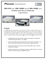
PMSVC control diagram
Inv.
Park
Pr07-24 Filter time of torque command
Pr07-26 Torque compensation gain
Pr10-31 I/F mode current c ommand (Id)
Torque
compensation
control
Pr05-40 PM motor Ld
Pr05-41 PM motor Lq
Pr05-43 PM motor Ke
Pr05-43 PM motor Ke
Pr05-39 Stator resistance
o f PM motor
d-axis voltage
command
q-axis voltage
command
d-axis current
feedback
q-axis current
feedback
Electrical angle
to
Pr10-32 PM s ensorless o bserver b andwidth
( high frequency area)
Pr10-34 PM s ensorless observer low-pass filter gain
3-phase current
feedback
Adjustment procedure
1. Set up PM motor control
Pr05-33=1 or 2
2. Set up motor parameter according to the nameplate on the motor
Pr01-01 Output Frequency of Motor 1
(
base frequency and motor rated frequency
)
Pr01-02 Output Voltage of Motor 1
(
base frequency and motor rated frequency
)
Pr05-34 Full-load current of Permanent Magnet Motor
Pr05-35 Rated Power of Permanent Magnet Motor
Pr05-36 Rated speed of Permanent Magnet Motor
Pr05-37 Pole number of Permanent Magnet Motor
3. Execute Auto-tuning
Set upPr05-00=13 for IPM motor tuning and press Run(static-tuning). When the tuning is
done, the following parameters will be obtained.
Pr05-39 Stator Resistance of PM Motor
Pr05-40 Permanent Magnet Motor Ld
Pr05-41 Permanent Magnet Motor Lq
Pr05-43 (V/1000rpm), the Ke parameter of PM motor ( this can be calculated
automatically according to power, current and speed of motor).
Pr10-52 Injection magnitude
Summary of Contents for CT2000 Series
Page 5: ...Chapter 1 Introduction CT2000 Series 1 2 Model Name VFD 750 CT 43 F 00 A6 Serial Number...
Page 22: ...Chapter 1 Introduction CT2000 Series 1 19 Digital Keypad KPC CC01 KPC CE01 Unit mm inch...
Page 23: ...Chapter 1 Introduction CT2000 Series 1 20 This page intentionally left blank...
Page 41: ...Chapter 4 Wiring CT2000 Series 4 6 This page intentionally left blank...
Page 71: ...Chapter 7 Optional Accessories CT2000 Series 7 18 Wall Mounting Embedded Mounting...
Page 87: ...Chapter 8 Optional Cards CT2000 Series 8 8 PG Card intallation...
Page 88: ...Chapter 8 Optional Cards CT2000 Series 8 9 Disconneting the extension card...
Page 92: ...Chapter 8 Optional Cards CT2000 Series 8 13 PG2 Wiring Diagram...
Page 95: ...Chapter 8 Optional Cards CT2000 Series 8 16 PG2 Wiring Diagram...
Page 117: ...Chapter 8 Optional Cards CT2000 Series 8 38 This page intentionally left blank...
Page 259: ...Chapter 12 Description of Parameter Settings CT2000 Series 12 1 03 11...
Page 260: ...Chapter 12 Description of Parameter Settings CT2000 Series 12 1 03 12...
Page 263: ...Chapter 12 Description of Parameter Settings CT2000 Series 12 1 03 15...
Page 266: ...Chapter 12 Description of Parameter Settings CT2000 Series 12 1 03 18...
Page 397: ...Chapter 13 Warning Codes CT2000 Series 13 8 This page intentionally left blank...
Page 407: ...Chapter 14 Fault Codes and Descriptions CT2000 Series 14 10 This page intentionally left blank...
Page 489: ...Chapter 16 PLC Function CT2000 Series 16 48 LD X1 Load Contact a of X1 OUT Y1 Drive Y1 coil...
Page 592: ...Chapter 16 PLC Function CT2000 Series 16 151...
Page 594: ...Chapter 16 PLC Function CT2000 Series 16 153...
Page 597: ...Chapter 16 PLC Function CT2000 Series 16 156 This page intentionally left blank...