63
O p e r a t i n g P r o c e d u r e s
Device Manager
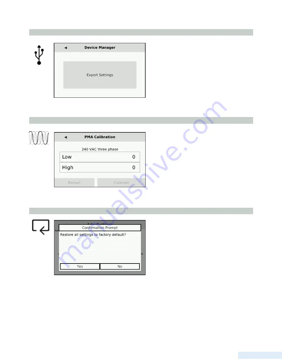
Selecting “Export Settings” will export the current TCU
configuration to the USB drive currently inserted in the
top drive. After this is done, a message prompt will
appear confirming the export was successful. For more
information on exporting settings to a USB, see below.
Calibrate PMA
Selecting the Calibrate PMA option displays a screen
with a space for entering both the current Low and High
voltage of the system. This setting is done at factory and
cannot be edited.
Utilizing the USB Ports for Configuration
When saving TCU settings for future use or transfer to another unit, a USB drive is needed. Insert the USB into the top port
on the face of the TCU. Then, navigate to the Advanced Settings and select the ‘Device Manager’ icon. On the screen that
appears, select ‘Export Settings.’ If the export to the USB drive was successful, a notification reading ‘Export successful’
will appear. If the export failed or no USB was available, the notification will read ‘Export failed.’
Factory Reset
Selecting the Factory Reset option displays a prompt
confirming the restoration of all current settings to
factory default. If ‘Yes’ is selected, all settings will
revert to the factory default. If ‘No’ is selected, the pop
up will clear and the screen will return to the Advanced
Settings menu. Note: factory reset does not reset Radio
Settings or TCU Settings.
Summary of Contents for TCU800
Page 1: ...Installation and Operation Manual T C U 8 0 0 Data Flow Systems Inc P r e l i m i n a r y ...
Page 2: ...Intentionally left blank ...
Page 4: ...D a t a F l o w S y s t e m s I n c Intentionally left blank ...
Page 8: ...ii Intentionally left blank ...
Page 10: ...ii Intentionally left blank ...
Page 56: ...46 C h a p t e r 5 Quick View Analog View Pump Statistics ...
Page 57: ...47 U s e r I n t e r f a c e Alarms Settings Screen 1 Settings Screen 2 ...
Page 58: ...48 C h a p t e r 5 Advanced Settings About ...
Page 77: ...67 O p e r a t i n g P r o c e d u r e s TCU Installed in Existing Control Panel ...
Page 87: ...77 M o d b u s S u p p o r t Figure 1 Figure 2 Figure 3 ...
Page 92: ...82 D a t a F l o w S y s t e m s I n c Appendix ...
Page 157: ...147 D a t a F l o w S y s t e m s I n c ...
Page 158: ...148 D a t a F l o w S y s t e m s I n c ...
Page 159: ...149 D a t a F l o w S y s t e m s I n c ...
Page 160: ......


