Description of choice:
If
Sum
[0] is selected, one of the adjusted preset references (parameters
215-218
Preset reference
) is summarized as a percentage of the refer-
ence range (Ref
MIN
- Ref
MAX
), added to the other external references.
If
Relative
[1] is selected, one of the added preset references (parameters
215-218
Preset reference
) is summarized as a percentage of the sum of
present external references.
If
External/preset
[2] is selected, it is possible via a digital input to shift
between external references or preset references. Preset references will
be a percentage value of the reference range.
NB!
If Sum or Relative is selected, one of the preset refer-
ences will always be active. If the preset references
are to be without influence, they must be set to 0%
(factory setting).
215
Preset reference 1 (PRESET REF. 1)
216
Preset reference 2 (PRESET REF. 2)
217
Preset reference 3 (PRESET REF. 3)
218
Preset reference 4 (PRESET REF. 4)
Value:
-100.00% - +100.00%
0.00%
of the reference range/external reference
Function:
Four different preset references can be programmed in parameters
215-218
Preset reference
.
The preset reference is stated as a percentage of the reference range
(Ref
MIN
- Ref
MAX
) or as a percentage of the other external references,
depending on the choice made in parameter 214
Reference function
. The
choice between preset references can be made via the digital inputs or
via serial communication.
Preset ref., msb
Preset ref. lsb
0
0
Preset ref. 1
0
1
Preset ref. 2
1
0
Preset ref. 3
1
1
Preset ref. 4
Description of choice:
Set the preset reference(s) that is/are to be the options.
219
Catch up/ Slow down reference
Value:
0.00 - 100% of the given reference
0.00%
Function:
In this parameter, the percentage value can be set which will either be
added to or deducted from the remote-controlled references.
The remote-controlled reference is the sum of preset references, ana-
logue references, pulse reference and any references from serial com-
munication.
Description of choice:
If
Catch up
is active via a digital input, the percentage value in parameter
219
Catch up/Slow down reference
will be added to the remote-control-
led reference.
If
Slow down
is active via a digital input, the percentage value in param-
eter 219
Catch up/Slow down reference
will be deducted from the re-
mote-controlled reference.
221
Current limit, I
LIM
Value:
0 - XXX.X % of par. 105
160 %
Function:
In this parameter, the maximum output current I
LIM
is set. The factory-
set value corresponds to the maximum output current I
MAX
. If the current
limit is to be used as motor protection, set the rated motor current. If the
current limit is set above 100% (the rated output current of the frequency
converter, I
INV.
), the frequency converter can only handle a load inter-
mittently, i.e. for short periods at a time. After the load has been higher
than I
INV.
, it must be ensured that for a period the load is lower than
I
INV.
Please note that if the current limit is set at a lower value than
I
INV.
, the acceleration torque will be reduced to the same extent.
Description of choice:
Set the required maximum output current I
LIM
.
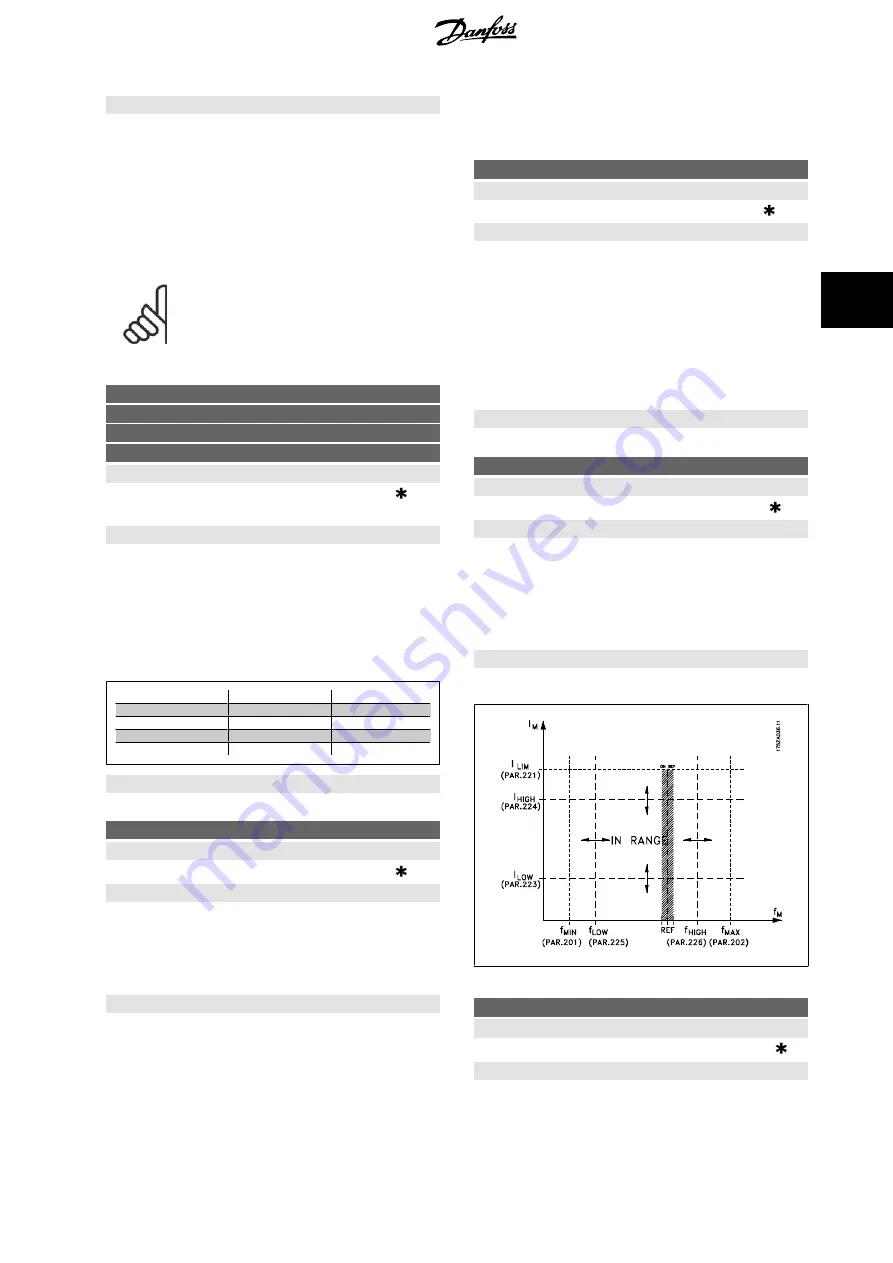
223
Warning: Low current, I
LOW
Value:
0.0 - par. 224
Warning: High current, I
HIGH
0.0 A
Function:
If the output current falls below the preset limit I
LOW
a warning is given.
Parameters 223-228
Warning functions
are out of function during ramp-
up after a start command and after a stop command or during stop.The
warning functions are activated when the output frequency has reached
the resulting reference. The signal outputs can be programmed to give a
warning signal via terminal 46 and via the relay output.
Description of choice:
The lower signal limit of the output current I
LOW
must be programmed
within the normal working range of the frequency converter.
224
Warning: High current, I
HIGH
Value:
0 - I
MAX
I
MAX
Function:
If the output current exceeds the preset limit I
HIGH
a warning is given.
Parameters 223-228
Warning functions
do not work during ramp-up after
a start command and after stop command or during stop. The warning
VLT
®
Decentral FCD 300 Design Guide
4 Programming
MG.90.S1.02 - VLT
®
is a registered Danfoss trademark
83
4


