3.5.12 Control of Mechanical Brake
No.
122 (optional function)
123 (optional function)
MBR+
MBR-
Mechanical brake (UDC=0.45 X Mains Voltage) Max 0.8 A
In lifting/lowering applications you need to be able to control an electromagnetic brake. The brake is controlled using the special mechanical brake control/
supply terminals 122/123.
When the output frequency exceeds the brake cut out value set in par. 138, the brake is released if the motor current exceeds the preset value in
parameter 140. When stopping the brake is engaged when the output frequency is less than the brake engaging frequency, which is set in par. 139.
If the frequency converter is at alarm status or in an overvoltage situation the mechanical brake is cut in immediately.
If not using the special mechanical brake control/supply terminals (122-123), select
Mechanical brake control
in parameter 323 or 341 for applications
with an electromagnetic brake.
A relay output or digital output (terminal 46) can be used. See
Connection of mechanical brake
for further details.
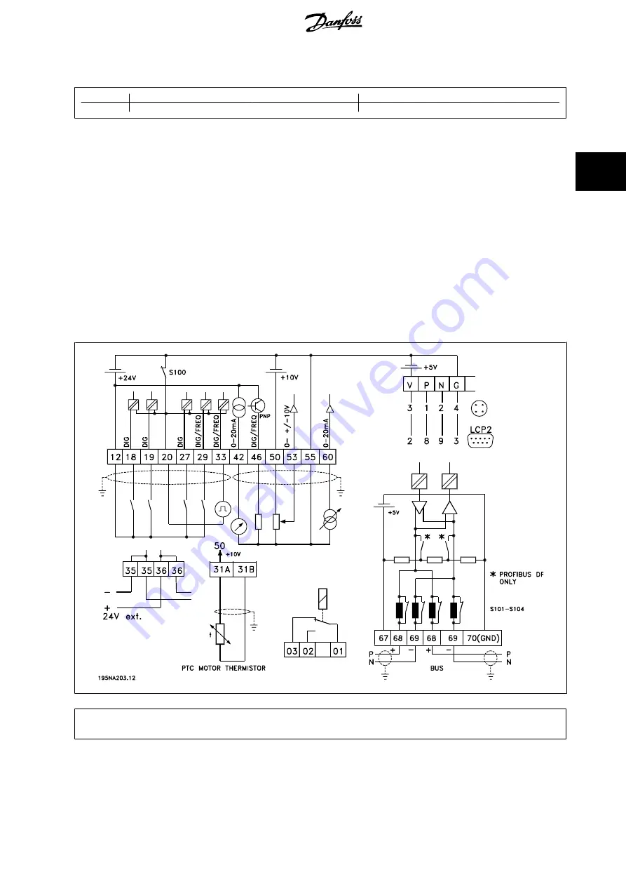
3.5.13 Electrical Installation, Control Cables
Control cables must be screened/armoured. The screen must be connected to the frequency converter chassis by means of a clamp. Normally, the screen
must also be connected to the chassis of the controlling unit (use the instructions for the unit in question). In connection with very long control cables
and analogue signals, in rare cases depending on the installation, 50/60 Hz earth loops may occur because of noise transmitted from mains supply cables.
In this connection, it may be necessary to break the screen and possibly insert a 100 nF capacitor between the screen and the chassis.
Switches S101-104
Bus line coils, leave switches ON
VLT
®
Decentral FCD 300 Design Guide
3 Installation
MG.90.S1.02 - VLT
®
is a registered Danfoss trademark
51
3


