


16-41
Cisco ONS 15454 DWDM Installation and Operations Guide, R6.0
April 2006
Chapter 16 Card Reference
16.5.3 OPT-BST-E Amplifier Card
16.5.2.2 OPT-BST Amplifier Card-Level Indicators
The OPT-BST amplifier has three card-level LED indicators, described in
.
16.5.2.3 OPT-BST Port-Level Indicators
You can find the status of the card ports using the LCD screen on the ONS 15454 fan-tray assembly. Use
the LCD to view the status of any port or card slot; the screen displays the number and severity of alarms
for a given port or slot. The OPT-BST amplifier has eight optical ports located on the faceplate.
MON RX is the output monitor port (receive section). MON TX is the output monitor port. COM RX is
the input signal port. LINE TX is the output signal port. LINE RX is the input signal port (receive
section). COM TX is the output signal port (receive section). OSC RX is the OSC add input port.
OSC TX is the OSC drop output port.
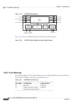
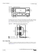
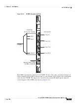
16.5.3 OPT-BST-E Amplifier Card
This section describes the OPT-BST-E amplifier card. The OPT-BST-E gain range is 8 to 23 dBm with
the tilt managed at 0 dBm in constant gain mode and output power mode. However, an extended gain
range of 23 to 26 dBm is available with the tilt unmanaged. See
Appendix B, “Hardware Specifications”
for detailed specification information. The OPT-BST-E is designed to support 64 channels at 50-GHz
channel spacing, but currently is limited to 32 channels at 100 GHz. The OPT-BST-E is a C-band DWDM
EDFA with OSC add-and-drop capability. When an ONS 15454 has an OPT-BST-E installed, it is only
necessary to have the OSCM to process the OSC. You can install the OPT-BST-E in Slots 1 to 6 and
12 to 17. To control the gain tilt, the OPT-BST-E is equipped with a built-in VOA.
The OPT-BST-E features include:
•
Fixed gain mode (with programmable tilt)
•
True variable gain
•
Extended gain (with unmanaged tilt)
P3
Output COM
LINE RX
P4
Output OSC
Table 16-22
OPT-BST Port Calibration (continued)
Photodiode
CTC Type Name
Calibrated to Port
Table 16-23
OPT-BST Card-Level Indicators
Card-Level Indicators
Description
Red FAIL LED
The red FAIL LED indicates that the card’s processor is not ready or that
there is an internal hardware failure. Replace the card if the red FAIL LED
persists.
Green ACT LED
The green ACT LED indicates that the OPT-BST is carrying traffic or is
traffic-ready.
Amber SF LED
The amber SF LED indicates a signal failure or condition such as LOS on
one or more of the card’s ports. The amber SF LED also illuminates when
the transmit and receive fibers are incorrectly connected. When the fibers are
properly connected, the light turns off.
Summary of Contents for ONS 15454 DWDM
Page 38: ...Figures xxxviii Cisco ONS 15454 DWDM Installation and Operations Guide R6 0 August 2005 ...
Page 54: ...Procedures liv Cisco ONS 15454 DWDM Installation and Operations Guide R6 0 August 2005 ...
Page 64: ... 64 Cisco ONS 15454 DWDM Installation and Operations Guide R6 0 August 2005 Chapter ...


