


15-33
Cisco ONS 15454 DWDM Installation and Operations Guide, R6.0
September 2005
Chapter 15 Shelf Hardware Reference
15.9 ONS 15454 ANSI Alarm Expansion Panel
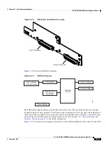
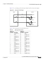
is a circuit diagram of the alarm inputs. (Inputs 1 and 32 are shown in the example.)
Figure 15-32
Alarm Input Circuit Diagram
lists the connections to the external alarm sources.
78473
Station
48 V
max. 2 mA
AEP/AIE
GND
VBAT–
VBAT–
Input 1
Input 48
Table 15-7
Alarm Input Pin Association
AMP Champ
Pin Number Signal Name
AMP Champ
Pin Number
Signal Name
1
ALARM_IN_1–
27
GND
2
GND
28
ALARM_IN_2–
3
ALARM_IN_3–
29
ALARM_IN_4–
4
ALARM_IN_5–
30
GND
5
GND
31
ALARM_IN_6–
6
ALARM_IN_7–
32
ALARM_IN_8–
7
ALARM_IN_9–
33
GND
8
GND
34
ALARM_IN_10–
9
ALARM_IN_11–
35
ALARM_IN_12–
10
ALARM_IN_13–
36
GND
11
GND
37
ALARM_IN_14–
12
ALARM_IN_15–
38
ALARM_IN_16–
13
ALARM_IN_17–
39
GND
14
GND
40
ALARM_IN_18–
15
ALARM_IN_19–
41
ALARM_IN_20–
16
ALARM_IN_21–
42
GND
17
GND
43
ALARM_IN_22–
Summary of Contents for ONS 15454 DWDM
Page 38: ...Figures xxxviii Cisco ONS 15454 DWDM Installation and Operations Guide R6 0 August 2005 ...
Page 54: ...Procedures liv Cisco ONS 15454 DWDM Installation and Operations Guide R6 0 August 2005 ...
Page 64: ... 64 Cisco ONS 15454 DWDM Installation and Operations Guide R6 0 August 2005 Chapter ...


