


16-16
Cisco ONS 15454 DWDM Installation and Operations Guide, R6.0
April 2006
Chapter 16 Card Reference
16.2.4 AIC-I Card
16.2.3.2 TCC2P Card-Level Indicators
The TCC2P faceplate has eight LEDs.
describes the two card-level LEDs on the TCC2P
faceplate.
16.2.3.3 Network-Level Indicators
describes the six network-level LEDs on the TCC2P faceplate.
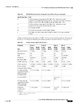
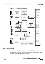
16.2.4 AIC-I Card
The optional Alarm Interface Controller–International (AIC-I) card provides customer-defined
(environmental) alarms and controls and supports local and express orderwire. It provides
12 customer-defined input and 4 customer-defined input/output contacts. The physical connections are
via the backplane wire-wrap pin terminals. If you use the additional alarm expansion panel (AEP), the
AIC-I card can support up to 32 inputs and 16 outputs, which are connected on the AEP connectors. The
AEP is compatible with ANSI shelves only. A power monitoring function monitors the supply voltage
(–48 VDC).
shows the AIC-I faceplate and a block diagram of the card.
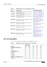
Table 16-9
TCC2P Card-Level Indicators
Card-Level LEDs
Definition
Red FAIL LED
This LED is on during reset. The FAIL LED flashes during the boot and
write process. Replace the card if the FAIL LED persists.
ACT/STBY LED
Green (Active)
Amber (Standby)
Indicates the TCC2P is active (green) or in standby (amber) mode. The
ACT/STBY LED also provides the timing reference and shelf control. When
the active TCC2P is writing to its database or to the standby TCC2P
database, the card LEDs blink. To avoid memory corruption, do not remove
the TCC2P when the active or standby LED is blinking.
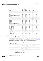
Table 16-10
TCC2P Network-Level Indicators
System-Level LEDs
Definition
Red CRIT LED
Indicates critical alarms in the network at the local terminal.
Red MAJ LED
Indicates major alarms in the network at the local terminal.
Amber MIN LED
Indicates minor alarms in the network at the local terminal.
Red REM LED
Provides first-level alarm isolation. The remote (REM) LED turns red when
an alarm is present in one or more of the remote terminals.
Green SYNC LED
Indicates that node timing is synchronized to an external reference.
Green ACO LED
After pressing the ACO button, the ACO LED turns green. The ACO button
opens the audible alarm closure on the backplane. ACO is stopped if a new
alarm occurs. After the originating alarm is cleared, the ACO LED and
audible alarm control are reset.
Summary of Contents for ONS 15454 DWDM
Page 38: ...Figures xxxviii Cisco ONS 15454 DWDM Installation and Operations Guide R6 0 August 2005 ...
Page 54: ...Procedures liv Cisco ONS 15454 DWDM Installation and Operations Guide R6 0 August 2005 ...
Page 64: ... 64 Cisco ONS 15454 DWDM Installation and Operations Guide R6 0 August 2005 Chapter ...


