


Chapter 9
9-8
Print speed when the throughput down control is executed
When the throughput down control is ON, print speed is switched step by step depending on the paper type or the temperature on the edge of the fixing sleeve etc.
Following shows the print speed list in case of the minimum throughput.
T-9-3
9.2.5 Feeding Speed Control
0019-5031
The machine switches the paper feeding speed depending on the type of paper fed in order to prevent a fixing failure.
The DC controller switches the paper feeding speed over 4 settings (1/1 speed, 4/5 speed, 1/2 speed, 2/5 speed) depending on the paper type specified by the main
controller.
T-9-4
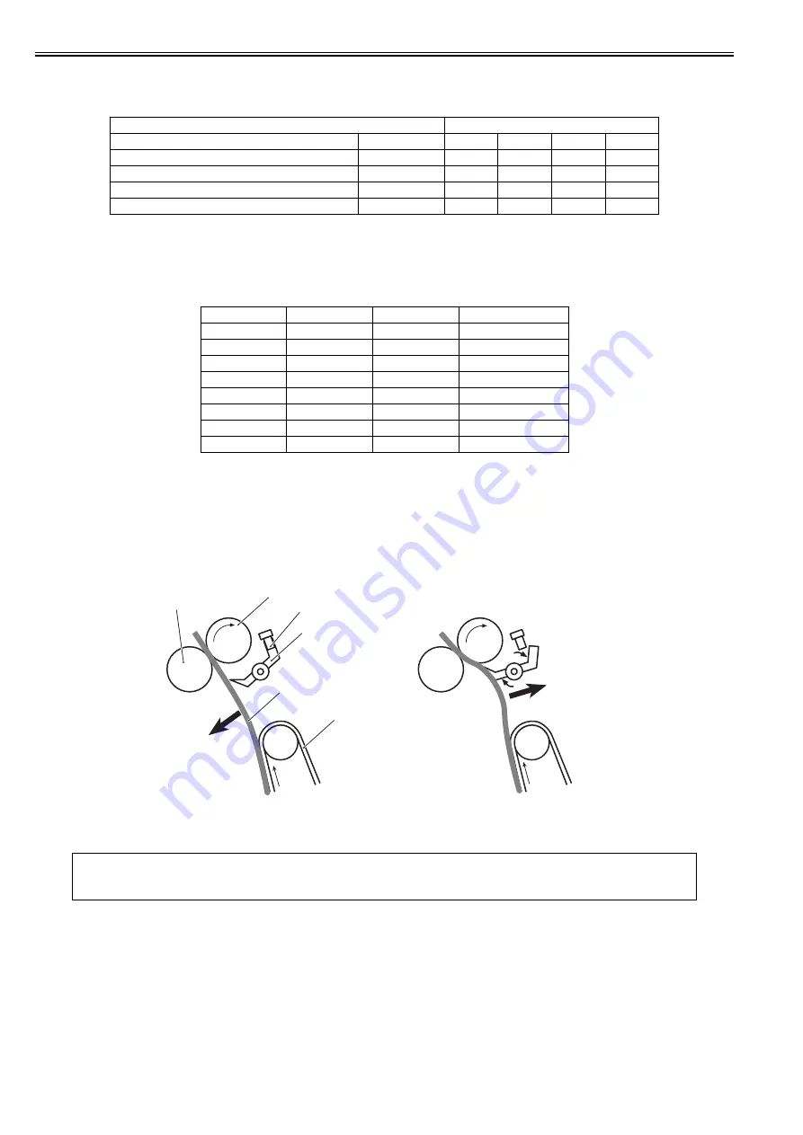
9.2.6 Warp Control
0019-5032
To prevent an image failure, it is necessary to keep the paper warped at an appropriate level between the fixing assembly and the ETB.
When the paper transport speed of the pressure roller is slower than that of the ETB, the paper warp increases, and an image defect or paper crease occurs. Con-
versely, the speed is faster than that of the ETB, the paper is pulled by the pressure roller, and a color displacement occurs in the sub-scanning direction.
The machine controls the rotational speed of the fixing motor (M1), which drives the pressure roller, to keep an appropriate level of paper warp.
When the paper is warped, the paper loop flag is pressed up, and the paper loop sensor (SR6001) is turned ON. In this case, the DC controller increases the rotational
speed of the fixing motor.
When the paper loop sensor is turned OFF, the DC controller determines that the level of paper warp is small and decreases the rotational speed of the fixing motor.
F-9-8
Paper
Print speed (ppm)
Type
Size
1st level
2nd level
3rd level
Last level
Plain paper/Plain paper H/Recycled paper/Color paper
B5R/A5R/EXECR
20.2
4.6
3.5
2.86
Heavy paper 1/Heavy paper 2/Rough paper
B5R/A5R/EXECR
16.1
4.4
3.4
2.76
Transparency
-
3.6
2.4
-
1.8
Postcard/Return postal card
-
10.1
3.8
3
2.5
Paper
Grammage
Paper type
Paper feeding speed
Plain paper
60 to 105 g/m2
Plain paper
1/1
Thick paper
105 to 120 g/m2
Thick paper 1
4/5
Thick paper
121 to 176 g/m2
Thick paper 2
4/5
Postcard
up to 190 g/m2
Postcard
1/2
Rough paper
-
Rough
2/5
Label
-
Label
4/5
Envelope
-
Envelope
4/5
Transparency
-
Transparency
2/5
MEMO:
If there are appropriate distance between the transfer unit and the fixing assembly in the product, this control is not necessary to make paper warped.
However, since the machine performs vertical feeding and it is necessary to minimize its height, no distance can be secured between the transfer unit and the fixing
assembly. Therefore, it is necessary to perform warp control.
Fixing pressure roller
Fixing sleeve
Paper loop sensor
Paper loop flag
ETB
Paper
Fixing pressure roller rotational speed is faster
than ETB feeding speed.
Fixing pressure roller rotational speed is slower
than ETB feeding speed.
Summary of Contents for iR C1020 Series
Page 1: ...Sep 8 2008 Service Manual iR C1020 Series iR C1021i ...
Page 2: ......
Page 6: ......
Page 18: ...Contents ...
Page 19: ...Chapter 1 Introduction ...
Page 20: ......
Page 22: ......
Page 57: ...Chapter 2 Installation ...
Page 58: ......
Page 60: ......
Page 73: ...Chapter 3 Basic Operation ...
Page 74: ......
Page 76: ......
Page 81: ...Chapter 4 Main Controller ...
Page 82: ......
Page 84: ......
Page 97: ...Chapter 5 Original Exposure System ...
Page 98: ......
Page 100: ......
Page 112: ......
Page 113: ...Chapter 6 Original Feeding System ...
Page 114: ......
Page 116: ......
Page 132: ......
Page 133: ...Chapter 7 Laser Exposure ...
Page 134: ......
Page 136: ......
Page 143: ...Chapter 8 Image Formation ...
Page 144: ......
Page 146: ......
Page 180: ......
Page 181: ...Chapter 9 Pickup and Feed System ...
Page 182: ......
Page 213: ...Chapter 9 9 29 F 9 79 1 2 3 ...
Page 214: ......
Page 215: ...Chapter 10 Fixing System ...
Page 216: ......
Page 218: ......
Page 233: ...Chapter 11 External and Controls ...
Page 234: ......
Page 263: ...Chapter 12 e maintenance imageWARE Remote ...
Page 264: ......
Page 266: ......
Page 275: ...Chapter 12 12 9 F 12 27 ...
Page 280: ......
Page 281: ...Chapter 13 Maintenance and Inspection ...
Page 282: ......
Page 284: ......
Page 286: ......
Page 287: ...Chapter 14 Measurement and Adjustments ...
Page 288: ......
Page 290: ......
Page 293: ...Chapter 15 Correcting Faulty Images ...
Page 294: ......
Page 296: ......
Page 317: ...Chapter 16 Error Code ...
Page 318: ......
Page 320: ......
Page 331: ...Chapter 16 16 11 ...
Page 332: ......
Page 333: ...Chapter 17 Special Management Mode ...
Page 334: ......
Page 336: ......
Page 343: ...Chapter 17 17 7 ...
Page 344: ......
Page 345: ...Chapter 18 Service Mode ...
Page 346: ......
Page 348: ......
Page 388: ......
Page 389: ...Chapter 19 Upgrading ...
Page 390: ......
Page 392: ......
Page 396: ...Chapter 19 19 4 3 Click Next F 19 4 4 Select a USB connected device and click Next F 19 5 ...
Page 397: ...Chapter 19 19 5 5 Click Start F 19 6 6 Click Yes F 19 7 Download will be started F 19 8 ...
Page 399: ...Chapter 19 19 7 ...
Page 400: ......
Page 401: ...Chapter 20 Service Tools ...
Page 402: ......
Page 404: ......
Page 407: ...Sep 8 2008 ...
Page 408: ......


