Chapter 7
7-4
7.2.2 Laser Light Emission Control
0020-0857
In this machine, the laser diode ON/OFF is controlled according to the laser light emission mode.
The laser light emission mode is determined based on the combination of the laser control signals (LD_CTL 0 to 2) that is output by the DC controller.
The laser driver IC receives the laser control signals from the DC controller and emits the laser diode according to the laser light emission mode.
7.2.3 Laser Light Intensity Control
0020-0858
In this machine, the laser light intensity is switched according to the rotational speed of the scanner motor.
The laser light intensity switch signal (LDPWRH) that is output by the DC controller controls switching the laser light intensity.
The laser driver IC receives the laser light intensity switch signal from the DC controller and switches the laser light intensity.
7.2.4 Image Masking Control
0019-5008
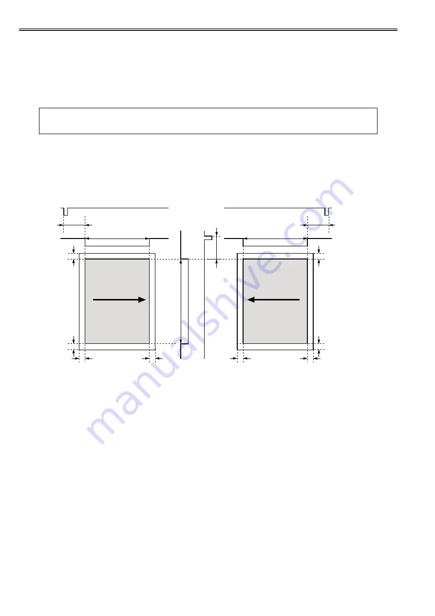
In the DC controller, the image masking control is performed to regulate laser beam emission in non-image area that BD detection is not performed on.
The DC controller puts the laser driver circuit into LD forced OFF mode while the laser beam scans the non-image area that BD detection is not performed on. This
is called the image masking status, and the laser diode does not emit light even if the video signals are sent because it is forcedly OFF in LD forced Off mode.
The timing to start the image masking control depends on the paper size information that DC controller receives from the main controller. (There is no cassette
paper size detection function in this equipment.)
F-7-3
- The colored area indicates the area where an image can be scanned by the laser beam.
- The times T1, T2, T3, T4 and T5 depend on the paper size.
- The T1 time depends on the color.
- If the main controller does not specify the paper size with a paper size command at manual feed pickup operation, the printer cannot detect the paper width. In
such a case, the T1 to T3 are automatically set for letter size but T5 is set according to the paper length detected by the manual feed paper sensor (SR707).
7.2.5 Failure Detection
0019-5009
In the DC controller, the failure in the laser diode is detected.
The laser driver IC converts the laser current of the laser diodes into voltage value (laser current output signal: PDOUT) during the initial APC period and sends it
to the DC controller.
If the voltage value equivalent to the laser current output signal is below the specified value, the DC controller presumes the laser diode failure, stops the printer
engine, and displays "E100 (optical unit failure)" on the control panel.
MEMO:
The process speed varies according to the paper type. (See 'Feed Speed Control' in Pickup and Feed System.)
When changing the process speed, the rotational speed of the scanner motor needs to be changed. If not switching the laser light intensity, a fault in image density
may occur.
2 mm
2 mm
2 m
m
2 m
m
/BDI
T3
T2
2 mm
2 mm
2 m
m
2 m
m
T2
/BDI
T1
T4
/T
OP
T5
Right/Left margin
masking
C/Bk Image masking
Y/M Image masking
T
op/Bottom
margin masking
Right/Left margin
masking
Scanning direction
Scanning direction
Summary of Contents for iR C1020 Series
Page 1: ...Sep 8 2008 Service Manual iR C1020 Series iR C1021i ...
Page 2: ......
Page 6: ......
Page 18: ...Contents ...
Page 19: ...Chapter 1 Introduction ...
Page 20: ......
Page 22: ......
Page 57: ...Chapter 2 Installation ...
Page 58: ......
Page 60: ......
Page 73: ...Chapter 3 Basic Operation ...
Page 74: ......
Page 76: ......
Page 81: ...Chapter 4 Main Controller ...
Page 82: ......
Page 84: ......
Page 97: ...Chapter 5 Original Exposure System ...
Page 98: ......
Page 100: ......
Page 112: ......
Page 113: ...Chapter 6 Original Feeding System ...
Page 114: ......
Page 116: ......
Page 132: ......
Page 133: ...Chapter 7 Laser Exposure ...
Page 134: ......
Page 136: ......
Page 143: ...Chapter 8 Image Formation ...
Page 144: ......
Page 146: ......
Page 180: ......
Page 181: ...Chapter 9 Pickup and Feed System ...
Page 182: ......
Page 213: ...Chapter 9 9 29 F 9 79 1 2 3 ...
Page 214: ......
Page 215: ...Chapter 10 Fixing System ...
Page 216: ......
Page 218: ......
Page 233: ...Chapter 11 External and Controls ...
Page 234: ......
Page 263: ...Chapter 12 e maintenance imageWARE Remote ...
Page 264: ......
Page 266: ......
Page 275: ...Chapter 12 12 9 F 12 27 ...
Page 280: ......
Page 281: ...Chapter 13 Maintenance and Inspection ...
Page 282: ......
Page 284: ......
Page 286: ......
Page 287: ...Chapter 14 Measurement and Adjustments ...
Page 288: ......
Page 290: ......
Page 293: ...Chapter 15 Correcting Faulty Images ...
Page 294: ......
Page 296: ......
Page 317: ...Chapter 16 Error Code ...
Page 318: ......
Page 320: ......
Page 331: ...Chapter 16 16 11 ...
Page 332: ......
Page 333: ...Chapter 17 Special Management Mode ...
Page 334: ......
Page 336: ......
Page 343: ...Chapter 17 17 7 ...
Page 344: ......
Page 345: ...Chapter 18 Service Mode ...
Page 346: ......
Page 348: ......
Page 388: ......
Page 389: ...Chapter 19 Upgrading ...
Page 390: ......
Page 392: ......
Page 396: ...Chapter 19 19 4 3 Click Next F 19 4 4 Select a USB connected device and click Next F 19 5 ...
Page 397: ...Chapter 19 19 5 5 Click Start F 19 6 6 Click Yes F 19 7 Download will be started F 19 8 ...
Page 399: ...Chapter 19 19 7 ...
Page 400: ......
Page 401: ...Chapter 20 Service Tools ...
Page 402: ......
Page 404: ......
Page 407: ...Sep 8 2008 ...
Page 408: ......


