Chapter 10
10-11
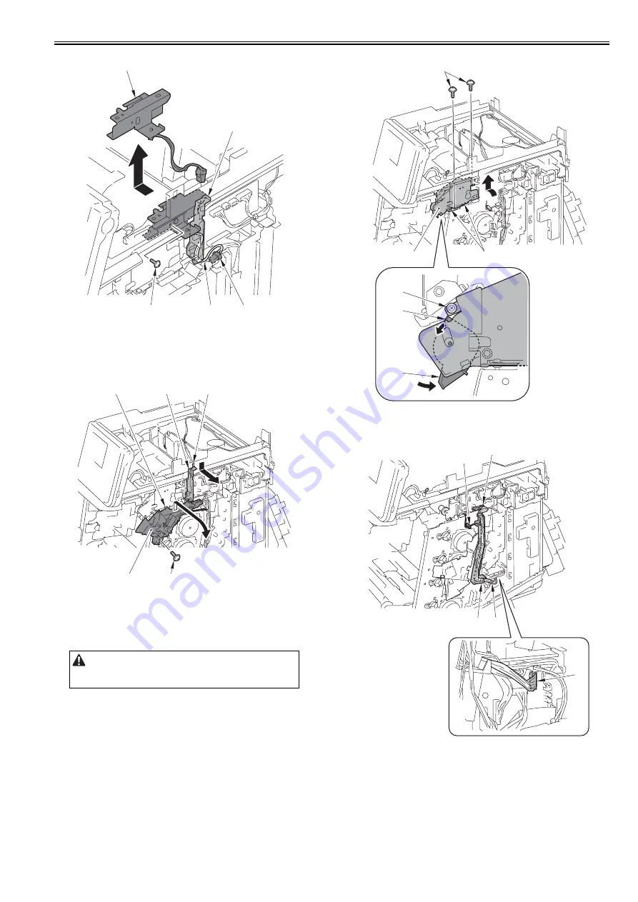
F-10-35
8) Remove the harness guide [1].
- 1 claw [2]
9) Remove the screw [3], move the interlock switch unit [4] in the direction
of the arrow and release the hook [5] to remove the interlock switch unit
[4].
F-10-36
10) Push the lever [1], and remove the screw [3] while lowering the projec-
tion [2].
11) Remove the 2 screws [4], move the duplex feed drive unit [5] in the di-
rection of the arrow and release the 2 projections [6] to remove the duplex
feed drive unit [5].
F-10-37
12) Disconnect the 2 connectors [1] and free the harness [2] from the harness
guide [3] and the wire saddle [4].
F-10-38
13) Remove the 3 screws [1], move the fixing drive unit [2] in the direction
of the arrow and release the projection [3] to remove the fixing drive unit
[2].
Point to Note at Work
The screw [3] is located at approx. 20mm rear side. Do not drop the screw
[3] when removing/tightening.
[2]
[1]
[4]
[3]
[5]
[3]
[4]
[5]
[1]
[2]
[5]
[6]
[4]
[1]
[2]
[3]
[1]
[1]
[4]
[3]
[2]
Summary of Contents for iR C1020 Series
Page 1: ...Sep 8 2008 Service Manual iR C1020 Series iR C1021i ...
Page 2: ......
Page 6: ......
Page 18: ...Contents ...
Page 19: ...Chapter 1 Introduction ...
Page 20: ......
Page 22: ......
Page 57: ...Chapter 2 Installation ...
Page 58: ......
Page 60: ......
Page 73: ...Chapter 3 Basic Operation ...
Page 74: ......
Page 76: ......
Page 81: ...Chapter 4 Main Controller ...
Page 82: ......
Page 84: ......
Page 97: ...Chapter 5 Original Exposure System ...
Page 98: ......
Page 100: ......
Page 112: ......
Page 113: ...Chapter 6 Original Feeding System ...
Page 114: ......
Page 116: ......
Page 132: ......
Page 133: ...Chapter 7 Laser Exposure ...
Page 134: ......
Page 136: ......
Page 143: ...Chapter 8 Image Formation ...
Page 144: ......
Page 146: ......
Page 180: ......
Page 181: ...Chapter 9 Pickup and Feed System ...
Page 182: ......
Page 213: ...Chapter 9 9 29 F 9 79 1 2 3 ...
Page 214: ......
Page 215: ...Chapter 10 Fixing System ...
Page 216: ......
Page 218: ......
Page 233: ...Chapter 11 External and Controls ...
Page 234: ......
Page 263: ...Chapter 12 e maintenance imageWARE Remote ...
Page 264: ......
Page 266: ......
Page 275: ...Chapter 12 12 9 F 12 27 ...
Page 280: ......
Page 281: ...Chapter 13 Maintenance and Inspection ...
Page 282: ......
Page 284: ......
Page 286: ......
Page 287: ...Chapter 14 Measurement and Adjustments ...
Page 288: ......
Page 290: ......
Page 293: ...Chapter 15 Correcting Faulty Images ...
Page 294: ......
Page 296: ......
Page 317: ...Chapter 16 Error Code ...
Page 318: ......
Page 320: ......
Page 331: ...Chapter 16 16 11 ...
Page 332: ......
Page 333: ...Chapter 17 Special Management Mode ...
Page 334: ......
Page 336: ......
Page 343: ...Chapter 17 17 7 ...
Page 344: ......
Page 345: ...Chapter 18 Service Mode ...
Page 346: ......
Page 348: ......
Page 388: ......
Page 389: ...Chapter 19 Upgrading ...
Page 390: ......
Page 392: ......
Page 396: ...Chapter 19 19 4 3 Click Next F 19 4 4 Select a USB connected device and click Next F 19 5 ...
Page 397: ...Chapter 19 19 5 5 Click Start F 19 6 6 Click Yes F 19 7 Download will be started F 19 8 ...
Page 399: ...Chapter 19 19 7 ...
Page 400: ......
Page 401: ...Chapter 20 Service Tools ...
Page 402: ......
Page 404: ......
Page 407: ...Sep 8 2008 ...
Page 408: ......


