Chapter 4
4-31
ADF controller PCB
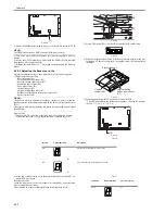
5) Try replacing the belt motor driver PCB. Is the problem corrected?
YES: Replace the belt motor drive PCB.
NO: Replace the ADF controller PCB.
4.4.1.2 E404
0011-3665
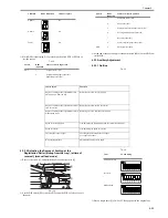
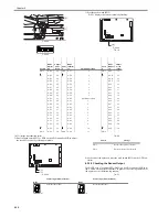
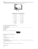
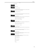
1) Set the DIP switch (SW1) on the ADF controller PCB as indicated.
F-4-149
Does the delivery motor (M5) rotate when the push switch (SW2) is pressed?
(To stop the operation, press the push switch (SW2) once again.)
YES: Go to step 3).
Delivery motor (M5)
2) Does it become good if the delivery motor is exchanged?
YES: End.
NO: Go to the next step.
After replacing the delivery motor, be sure to perform "Adjusting the Sensors and the Delivery Motor."
Delivery Motor Clock Sensor (PI11), ADF Controller PCB
3) Set the meter range to 10 VDC. Does the voltage between connectors J3-2 (+) and J3-1 (-) on the ADF controller PCB alternate between 0 and 5 V when the
delivery motor is rotated by hand?
NO: Replace the delivery motor clock sensor (PI11).
YES: Replace the ADF controller PCB.
4.4.1.3 E405
0011-3666
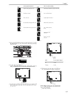
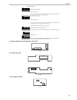
1) Set the DIP switch (SW1) on the ADF controller PCB as indicated.
F-4-150
Does the separation motor (M4) rotate when the push switch (SW2) is pressed?
(To stop the operation, press the push switch (SW2) once again.)
YES: Go to step 3).
Separation motor (M4)
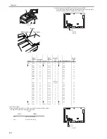
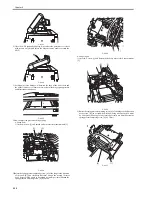
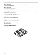
2) Disconnect the connector (J8) of the ADF controller PCB. Set the meter range to x1 ohm, and connect the meter probe to the connectors on the cable side as
indicated. Is the resistance about 5.0 ohm?
F-4-151
NO: Replace the separation motor (M4).
Separation motor clock sensor (PI2), ADF controller PCB
3) Set the meter range to 10 VDC. Does the voltage between connectors J12-5 (+) and J12-4 (-) on the ADF controller PCB alternate between 0 and 5 V?
NO: Replace the separation motor clock sensor (PI2).
YES: Replace the DADF controller PCB.
4.4.1.4 E410
0011-3667
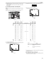
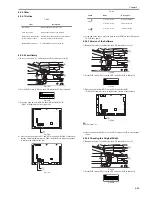
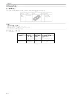
1) Set the DIP switch (SW1) on the ADF controller PCB as indicated.
F-4-152
Does the motor (M3) rotate when the push switch SW2 and then the push switch SW3/SW4 are pressed?
(To stop the operation, press the push switch (SW2) once again.)
YES: Go to step 3).
Pickup motor (M3)
2) Does it become good if the pickup motor is exchanged?
YES: End.
NO: Go to the next step.
Summary of Contents for DADF-Q1
Page 1: ...Aug 24 2007 Service Manual Feeder DADF Q1 ...
Page 2: ......
Page 6: ......
Page 11: ...Chapter 1 Specifications ...
Page 12: ......
Page 14: ......
Page 18: ......
Page 19: ...Chapter 2 Functions ...
Page 20: ......
Page 22: ......
Page 75: ...Chapter 3 Parts Replacement Procedure ...
Page 76: ......
Page 107: ...Chapter 4 Maintenance ...
Page 108: ......
Page 149: ...Chapter 5 Error Code ...
Page 150: ......
Page 152: ......
Page 154: ......
Page 155: ...Aug 24 2007 ...
Page 156: ......

