Chapter 4
4-23
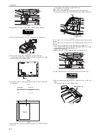
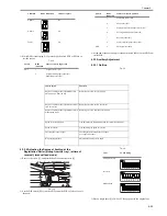
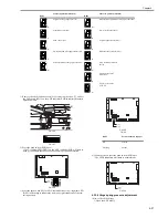
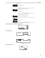
1) While DSP1 is indicating 'NG', press the push switch SW3 or SW4 to se-
lect the sensor.
T-4-12
2) At the end of the operation, press the push switch (SW2) on the ADF con-
troller PCB.
4.3.3 Auxiliary Adjustmant
4.3.3.1 Outline
0011-3507
T-4-13
4.3.3.2 Adjusting the Degree of Arching at the
Registration Roller (pickup from the tray), (at time of
reversal), (manual feed mode)
0011-3508
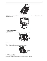
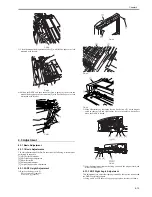
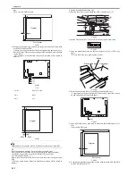
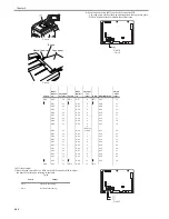
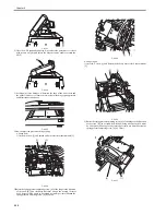
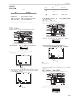
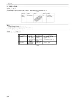
1) Remove the screw [1], and detach the ADF controller cover [2].
F-4-113
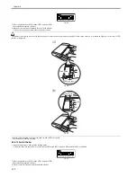
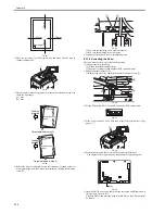
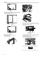
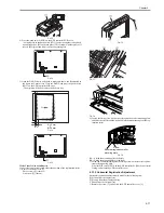
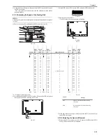
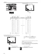
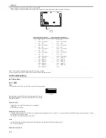
2) Set the DIP switch (SW1) on the ADF controller PCB as follows to suit
the need:
T-4-14
3) Place a single sheet [1] of A4 or LTR copy paper in the original tray.
Alarm 1
No
Alarm 2
Yes
Faulty
Yes
Switch
DSP1
indication
Sensor or motor in question
SW3
1
Original sensor (S6)
2
Original trailing edge sensor (S7)
Separation sensor (S4)
Condition
DSP1 indication
Check or replace
3
Separation sensor (S4)
4
Skew sensor (S5)
5
Pre-registration roller paper sensor (S2)
6
Post-registration paper sensor (S3)
7
Reversal sensor (S1)
8
Pre-last original paper sensor (S8)
SW4
9
Delivery motor (M5)
Switch
DSP1
indication
Sensor or motor in question
Item to adjust
Function
Degree of arching at the registration roller
when pickup is from the tray
Removing the skew for CW pickup
Degree of arching at the registratoin roller at
time of reversal
Removing the skew at time of reversal
Degree of arching at the registration roller in
manual feed mode
Removing the skew in manual feed mode
Speed of the feeding belt
Fine-adjusting the reproduction ratio for stream reading mode
Speed of reversal
Fine-adjusting the speed of reversal
Checking the sensor output
Checking the presence/absence of paper
over a specific sensor
Hinge spring pressure
Adjustment of a hinge hold angle
[1]
[2]
Item
Switch setting
Pickup from tray
Reversal
Manual feed
Summary of Contents for DADF-Q1
Page 1: ...Aug 24 2007 Service Manual Feeder DADF Q1 ...
Page 2: ......
Page 6: ......
Page 11: ...Chapter 1 Specifications ...
Page 12: ......
Page 14: ......
Page 18: ......
Page 19: ...Chapter 2 Functions ...
Page 20: ......
Page 22: ......
Page 75: ...Chapter 3 Parts Replacement Procedure ...
Page 76: ......
Page 107: ...Chapter 4 Maintenance ...
Page 108: ......
Page 149: ...Chapter 5 Error Code ...
Page 150: ......
Page 152: ......
Page 154: ......
Page 155: ...Aug 24 2007 ...
Page 156: ......

