background image

Chapter 3  

3-4

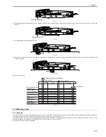
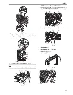
F-3-22

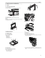
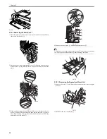
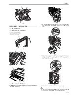
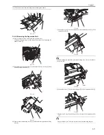
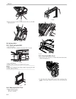
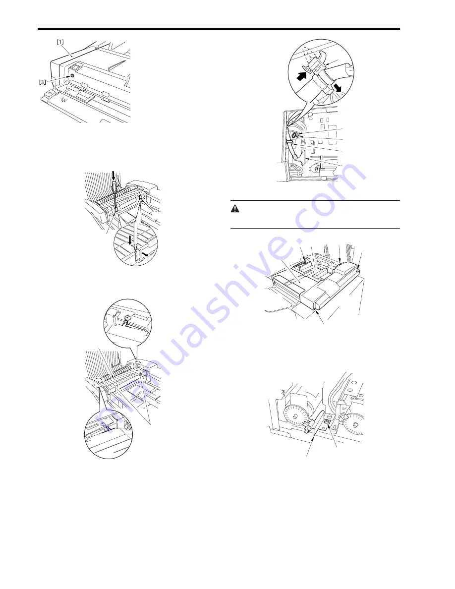
3.3.2.2 Removing the Main Cover

0011-8130

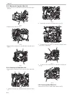
1) Open the upper cover, and insert a screwdriver from above the hook; then,

remove the two hooks [1].
 

F-3-23

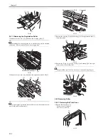
2) Free the hook of the pickup assembly cover [2] from the right stay; then,

detach it while paying attention to the hooks on the front and rear side
plates.

F-3-24

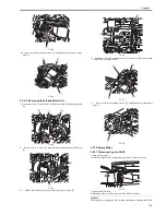
3) When you have removed the ADF controller cover, disconnect the con-

nector [3] of the ADF controller PCB; then, remove the screw [4], and re-
move the grounding wire [5]. Free the harness from the wire saddle [6],
and detach the other saddle [7].

F-3-25

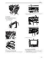
4) Remove the four screws [1], and detach the main cover [2].

 The main cover is fitted with the original tray [3], and cables are connected
to it. Take extra care when removing it not to damage the cables.

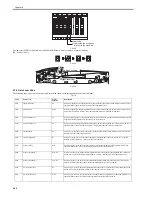
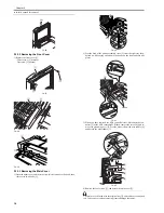
F-3-26

3.3.2.3 Removing the Separation Motor Unit

0011-8131

1) Remove the screw [1], and detach the separation motor sensor support

plate [2].

F-3-27

2) Disconnect the two connectors [1].

[1]

[1]

[2]

Hooks

Push.

Freed.

[5]

[7]

[4]

[6]

[3]

[1]

[1]

[1]

[1]

[3]

[2]

[2]

[1]

Summary of Contents for DADF-Q1

Page 1: ...Aug 24 2007 Service Manual Feeder DADF Q1 ...

Page 2: ......

Page 3: ... need arises In the event of major changes in the contents of this manual over a long or short period Canon will issue a new edition of this manual The following paragraph does not apply to any countries where such provisions are inconsistent with local law Trademarks The product names and company names used in this manual are the registered trademarks of the individual companies Copyright This ma...

Page 4: ...quiring care to avoid combustion fire Indicates an item prohibiting disassembly to avoid electric shocks or problems Indicates an item requiring disconnection of the power plug from the electric outlet Indicates an item intended to provide notes assisting the understanding of the topic in question Indicates an item of reference assisting the understanding of the topic in question Provides a descri...

Page 5: ...sed to indicate Low The voltage value how ever differs from circuit to circuit In addition the asterisk as in DRMD indicates that the DRMD signal goes on when 0 In practically all cases the internal mechanisms of a microprocessor cannot be checked in the field Therefore the operations of the microprocessors used in the machines are not discussed they are explained in terms of from sensors to the i...

Page 6: ......

Page 7: ...ecting the Presence Absence of an Original in the Manual Feeder 2 14 2 4 Document Pickup Separation 2 15 2 4 1 Outline 2 15 2 4 2 Moving Up Down the Pickup Roller Unit 2 15 2 4 3 Switching the Separation Pressure 2 17 2 4 4 Separation Sensor S4 and Skew Sensor S5 2 18 2 4 5 Controlling the Pickup Motor M3 2 19 2 4 6 Controlling the Separation Motor M4 2 19 2 4 7 Sequence of Operations 2 20 2 5 Doc...

Page 8: ... 3 3 4 Removing the Delivery Motor 3 7 3 3 4 Separation Motor Unit 3 7 3 3 4 1 Removing the Front Cover 3 7 3 3 4 2 Removing the Main Cover 3 7 3 3 4 3 Removing the Separation Motor Unit 3 8 3 3 5 Belt Motor Unit 3 9 3 3 5 1 Removing the Front Cover 3 9 3 3 5 2 Removing the Main Cover 3 9 3 3 5 3 Removing the Separation Motor Unit 3 10 3 3 5 4 Removing the Pickup Motor Unit 3 10 3 3 5 5 Removing t...

Page 9: ...ced Parts 4 1 4 2 1 1 Periodiccally Replaced Parts 4 1 4 2 2 Durables 4 1 4 2 2 1 Durables 4 1 4 2 3 Periodical Servicing 4 2 4 2 3 1 Scheduled Servicing Chart 4 2 4 2 4 Cleaning 4 3 4 2 4 1 Outline 4 3 4 2 4 2 Cleaning the Separation Assembly 4 3 4 2 4 3 Cleaning the Registration Roller 4 4 4 2 4 4 Copyboard Glass 4 5 4 2 4 5 Belt Assembly 4 6 4 2 4 6 Original Trailing Edge Sensor 4 6 4 2 4 7 Ori...

Page 10: ...stment 4 27 4 3 4 Other 4 29 4 3 4 1 Outline 4 29 4 3 4 2 Jam History 4 29 4 3 4 3 Version of the Software 4 29 4 3 4 4 Checking the Original Width 4 29 4 4 Troubleshooting 4 30 4 4 1 Error Code 4 30 4 4 1 1 E402 4 30 4 4 1 2 E404 4 31 4 4 1 3 E405 4 31 4 4 1 4 E410 4 31 4 4 1 5 E420 4 32 4 5 Outline of Electrical Components 4 32 4 5 1 Sensors 4 32 4 5 2 Motors Clutches and Solenoids 4 33 4 5 3 PC...

Page 11: ...Chapter 1 Specifications ...

Page 12: ......

Page 13: ...tents Contents 1 1 Product Specifications 1 1 1 1 1 ADF Specifications 1 1 1 2 Names of Parts 1 2 1 2 1 External View 1 2 1 2 2 Cross Section 1 3 1 3 Using the Machine 1 3 1 3 1 Original Set Indicator 1 3 ...

Page 14: ......

Page 15: ...heets In below 80g m2paper The manuscripts exceeding 80g m2 are base weight conversion A5 A4 B5 STMT LTR A4R B5R LTRR large size 100 sheets 80 g m2 or less If heavier than 80 g m2 conversion used If longer than 432 mm 1 sheet A3 B4 LGL 279 4X431 8mm 11 X17 Original reference tray center manual feeder rear Original reading stream single sided fixed Pre cycle end no Control panel no Display no Origi...

Page 16: ...unit by way of reader unit Weight 21 5 kg approx Not including delivery tray Dimensions 646 W x 569 5 D x 143 H mm Not including delivery tray Power consumption 100 W or less during operation Operating noise sound pressure host machine 3 dB Host machine ADF finisher alone 72 dB sound quality 10 78 sone 85 ipm DF opening closing noise impact sound pressure 70 dB Operating noise same as host machine...

Page 17: ...ve the original from the copyboard glass if found 4 Put the originals back into initial sequence and place the stack in the DADF 1 Reversing roller B member 13 Delivery roller B member 2 Reversing roller B 14 Delivery roller 3 Reversing flapper 15 Delivery guide flapper 4 Registration pressure roller 16 Feeding belt 5 Registration roller 17 Stopper plate 6 Pull off roller 18 Separation belt 7 Pull...

Page 18: ......

Page 19: ...Chapter 2 Functions ...

Page 20: ......

Page 21: ...ickup Roller Unit 2 15 2 4 3 Switching the Separation Pressure 2 17 2 4 4 Separation Sensor S4 and Skew Sensor S5 2 18 2 4 5 Controlling the Pickup Motor M3 2 19 2 4 6 Controlling the Separation Motor M4 2 19 2 4 7 Sequence of Operations 2 20 2 5 Document Feeding Delivery 2 20 2 5 1 Outline 2 20 2 5 2 Controlling the Belt Motor M2 2 21 2 5 3 Controlling the Delivery Motor M5 2 22 2 6 Feeding Unit ...

Page 22: ......

Page 23: ...als from sensors and the host ma chine and generates appropriate signals to drive such loads as motors and solenoids at such times as programmed in advance F 2 1 CPU Q1 ROM IC1 EEPROM IC2 RAM Q4 D A Q9 IPC Q2 5V 24V 5R 24R Power supply PCB Copier Solenoid Clutch Original indicator LED PCB Sub tray PCB Reversal motor driver PCB Belt motor driver PCB Motor Sensor Motor Motor ADF controller PCB DC5V ...

Page 24: ...of the separation motor When the paper cover is closed 1 When paper is present 1 Pulses according to the rotation speed of the registration roller When the upper cover is closed 1 When the pickup roller is in home position 1 When the pickup roller is on paper 1 When the pickup roller is on paper 1 When the DADF is closed 1 Pulses according to the rotation speed of the delivery motor When paper is ...

Page 25: ... registration roller paper sensor Post registration roller paper sensor Separation sensor Skew sensor Original sensor light receiving Original sensor light emitting Original trailing edge sensor Manual feed registration roller paper sensor ADF controller PCB Reference signal for paper detection When paper is present 0 Reference signal for paper detection When paper is present 0 Reference signal fo...

Page 26: ... 10 9 8 1 2 3 4 5 6 24V 24V A A B B 1 2 3 4 5 6 24V 24V A A B B 4 6 13 12 11 10 9 8 M1 J8 1 2 2 1 J2 11 12 2 1 2 1 1 2 11 12 M5 M4 J24 J81 J21 FM1 J601 J602 J21 J22 J101 FAN 24V LOCK J9 6 7 8 3 2 1 1 2 3 J93 J92 J91 J102 CL SL1 SL2 SL3 SL4 24V 5V M2OB M2OA M2OB M2OA B Vref J7 8 10 1 2 3 4 5 6 M2 J71 J72 Separation clutch Reversal solenoid Stopper plate solenoid 2 position Pre reversal solenoid Del...

Page 27: ...er solenoid drive signal 2 SL2D2 Stopper plate solenoid signal 1 SL2D1 Pickup motor drive signal Belt motor drive signal Belt motor clock signal BTCLK Reversal motor drive signal Reversal solenoid drive signal SL3D Registration roller clock signal TRCLK Delivery solenoid drive signal 1 SL4D Delivery motor drive signal Delivery motor clock signal EJCLK CL Delivery solenoid drive signal 1 SL4D ADF c...

Page 28: ...t up reverses it once again after copying and delivers it Fixed reading Double sided original to double sided copy Double sided original to single sided copy Fixed reading 3 Manual feeder pickup delivery Picks up an original from the manual feeder and delivers it after copying Manual copy Fixed reading PI 2 PI 1 PI 5 PI 11 SL3 SL1 SL2 SL4 M5 Pre reversal solenoid drive signal SL1D Separation motor...

Page 29: ...ng is an outline of the flow of originals Pickup F 2 7 Scan F 2 8 Delivery F 2 9 2 2 4 Pre Reversal Reversal Delivery 0011 2235 The following is an outline of the flow of originals F 2 10 Picking up Pre reversing Feeding Copying the 1st side Moving To next page ...

Page 30: ... 2 2 5 Manual Feeder Pickup Delivery 0011 2237 The following is an outline of the flow of originals F 2 12 Reversing Copying the 2nd side Delivering From previous page Picking up Stopping Switching back Copying Delivering ...

Page 31: ... detection signal DTS to the ADF controller PCB which in response turns on the Original Set indicator Item Description Sensor used notation Presence absence of an original Identifies the presence absence of an original on the original tray Original sensor S6 Original size 1 Identifies the size of the original placed in the original tray as to being large size or small size Original trailing edge s...

Page 32: ...hich time the DADF identifies the original as being large size The DADF sends original size data small size or large size to the copier which uses the data to determine the point at which the scanner is stopped for stream reading Small size A5 A4 B5 STMT LTR Large size A4R B5R A3 B4 LTRR LGL 279 4X431 8mm 11 X17 ADF controller PCB S6 light receiving side S6 light emitting side S6 light receiving s...

Page 33: ...which uses the input to determine the width of the original The following table shows the states of the contact plates in relation to default sizes the states other than those indicated are assumed to indicate the presence of an original which is not of a default size F 2 16 T 2 3 Default size SSW0 SSW1 SSW2 SSW3 SSW4 A5 A4R ON ON OFF ON ON ON OFF OFF ON ON A4 A3 ON OFF OFF ON OFF ON OFF OFF OFF O...

Page 34: ...opy paper size to suit the identified size of the original The following tables show the default sizes in relation to the sizes detected by the DADF T 2 4 A and A B Configuration T 2 5 B5 B4 ON OFF ON OFF ON ON OFF ON OFF OFF STMT LTRR LGL ON ON ON OFF ON ON ON OFF OFF ON LTR 279 4X431 8mm 11 X17 ON ON OFF OFF OFF ON ON ON OFF OFF unit mm Default size Original length Original width B5R 237 to 297 ...

Page 35: ...13 to 220 9 LTRR 259 to 309 FOOLSCAP 310 to 343 LGL 343 to 396 LTR 196 to 256 274 4 to 284 4 279 4X431 8 11 X17 412 to 472 A size outside of the above ranges will be identified as a non default size unit mm Default size Original length Original width B5R 237 to 297 170 to 187 A5 129 to 189 205 to 213 A4R 277 to 337 STMT 120 to 180 213 to 220 9 LTRR 259 to 309 FOOLSCAP 317 to 343 LGL 343 to 396 B5 ...

Page 36: ...T 2 7 F 2 19 2 3 5 Detecting the Presence Absence of an Original in the Manual Feeder 0011 2325 The presence absence of an original in the manual feeder is detected using the manual set sensor PI12 When an original is placed in the manual feeder the original pushes the sensor flag causing the sensor flag to reach the sensor enabling the DADF to assume the presence of an original in the manual feed...

Page 37: ...tch CL The separation assembly is equipped with a separation sensor S4 and a skew sensor S5 to monitor the movement of originals F 2 21 2 4 2 Moving Up Down the Pickup Roller Unit 0011 2328 a Outline The DADF is equipped with two pickup roller units each designed to move up down between home position and the surface of the stack of originals The pickup roller unit is moved up down by the pickup mo...

Page 38: ...e down the separation clutch CL and the separation motor M3 start to move the 1st original to the separation assembly Stop position Operation Related sensor notation Home position Waits until the next copying operation Pickup roller home position sensor PI7 Wait position Waits until the next pickup position Pickup height sensor 1 2 PI8 9 Pulse control of pickup motor M3 Pickup position Picks up or...

Page 39: ...ls to pick up the 2nd original F 2 26 2 4 3 Switching the Separation Pressure 0011 2330 The DADF s separation assembly is equipped with a separation pressure switching mechanism which enables switching between two settings low or high The separation pressure may be switched by operating the separation pressure lever located in front of the separation assembly When the lever is operated the positio...

Page 40: ...sensors are arranged in a single row in front rear direction An original is identified as moving askew if a discrepancy in timing is detected when it moves past these sensors If the discrepancy is an equivalent of 10 mm the DADF will assume that the original is moving askew at which point it stops its operation to protect the original and causes the copier to indicate a jam message Item Sensor use...

Page 41: ...steps from 0 to 100 PICKSTBY is a motor standby signal and is used to turn off the motor drive circuit during which time no phase signal is sent to the motor Error code E410 fault in the pickup motor M3 fault in the pickup roller height sensor PI8 fault in the pickup roller height sensor PI9 fault in the pickup roller home position sensor PI7 fault in the ADF controller PCB 2 4 6 Controlling the S...

Page 42: ...ion motor if the separation motor stop signal continues indicating an error code E405 on the host machine s display Error code E405 fault in the separation motor M4 fault in the separation clock sensor PI2 fault in the ADF controller PCB 2 4 7 Sequence of Operations 0011 2347 Picking Up Separation Originals F 2 32 2 5 Document Feeding Delivery 2 5 1 Outline 0011 2385 Originals are moved by rotatin...

Page 43: ...to the belt motor driver PCB which in turn controls the motor as instructed by these signals T 2 10 Error code E402 fault in the belt motor M2 fault in the belt motor clock sensor PI1 fault in the ADF controller PCB Signals Description INA phase control direction and speed of rotation INB phase control direction and speed of rotation IN_A phase control direction and speed of rotation IN_B phase co...

Page 44: ...e delivery motor 2 6 Feeding Unit 2 6 1 Outline of CW Pickup Delivery 0011 7302 The machine uses CW pickup delivery both in fixed reading mode and in stream reading mode T 2 12 The machine uses fixed reading mode for the following the magnification is set to 201 or higher the machine has identified the original as being of a non default size Stream reading is disabled in the host machine s service...

Page 45: ...belt over a specific distance after its trail edge has moved past the pre registration roller sensor S2 determining the original stop position F 2 38 4 The host machine starts printing operation using its scanner F 2 39 5 When the host machine s scanner starts to move in reverse the machine rotates the transport belt in reverse to move the 1st original in the direction of delivery At the same time...

Page 46: ... the case of a large size original the machine controls the distance between sheets so that only a single original is on the copyboard glass at a time in step 6 Pre registration roller paper sensor S2 2nd original 1st original ...

Page 47: ...tch CL Reversal motor M1 Belt motor M2 Delivery motor M5 UP DOWN UP DOWN UP UP DOWN separates 1st original moves 1st original in delivery direction reads 2nd original separates 3rd original delivers 1st original moves 2nd original in delivery direction reads 3rd direction delivers 2nd original moves 3rd original in delivery direction delivers 3rd original reads 1st original separates 2nd original ...

Page 48: ... 2 44 3 The machine places the 1st original on the copyboard The host machine starts to scan the original F 2 45 4 The machine uses the transport belt and the delivery roller to discharge the 1st original The host machine moves the scanner in reverse F 2 46 5 When the 1st original is fully discharged the machine starts pickup of the 2nd original F 2 47 6 Goes back to step 2 above and repeats the s...

Page 49: ...the registration roller to remove the skew For details of pickup operation see Original Pickup Separation F 2 49 Start key ON Original sensor S6 Pickup roller home position sensor PI 7 Pickup roller height sensor 1 2 PI 8 9 Stopper plate solenoid SL2 Pickup motor M3 Separation motor M4 Separation clutch CL Reversal motor M1 Belt motor M2 Delivery motor M5 UP DOWN UP UP DOWN picks up 1st original r...

Page 50: ...dge of the original has moved past the pre registration roller paper sensor S2 the machine sends the image lead edge signal to the host machine In response to the signal the host machine starts to read the original At this time the machine starts to move the 2nd original F 2 52 5 The machine rotates the transport belt to move the 2nd original If the read signal arrives from the host machine before...

Page 51: ...standby separates 3rd original discharges 1st original reads 2nd original holds 3rd original in standby discharges 2nd original reads 3rd original discharges 3rd original A4 Single Sided Originals Stream Reading does not stop 2nd original before reading stops 3rd original before reading Original sensor S6 Pickup roller home position sensor PI 7 Pickup roller height sensor 1 2 PI 8 9 Stopper plate ...

Page 52: ...iginal has moved past the pre registration roller paper sensor S2 the machine sends the image lead edge signal to the host machine In response to the signal the host machine starts to read the original At this time the machine also moves the 2nd original F 2 58 5 The machine rotates the transport belt motor to move the 2nd original If the read signal arrives from the host machine before the 2nd or...

Page 53: ...ler height sensor 1 2 PI 8 9 Stopper plate solenoid SL2 Pickup motor M3 Separation motor M4 Separation clutch CL Reversal motor M1 Belt motor M2 Delivery motor M5 UP DOWN UP UP DOWN separates 1st original reads and discharges 1st original moves 2nd original to standby position reads 2nd original discharges 2nd original moves 1st original to standby position separates 2nd original A3 2 Single Sided...

Page 54: ...r which the 1st original moves after it has moved past the pre registration roller paper sensor S2 F 2 63 4 The machine rotates the transport belt to move the original over a specific distance and discharges it reading takes place here F 2 64 5 When the 1st original has fully been discharged the machine starts pickup of the 2nd original F 2 65 6 The machine goes back to step 2 and repeats the subs...

Page 55: ...the original using its scanner when the machine places the original on the copyboard glass Start key ON Original sensor S6 Pickup roller home position sensor PI 7 Pickup roller height sensor 1 2 PI 8 9 Stopper plate solenoid SL2 Pickup motor M3 Separation motor M4 Separation clutch CL Reversal motor M1 Belt motor M2 Delivery motor M5 UP DOWN UP UP DOWN picks up 1st original reads and discharges 1s...

Page 56: ...ces it on the copyboard glass F 2 70 F 2 71 5 The host machine scans the back of the 1st original F 2 72 6 The 1st original turns over the 1st original once again F 2 73 7 The machine discharges the 1st original F 2 74 8 The machine places the 2nd original on the copyboard glass 1st original 1st original 1st original 1st original 1st original 1st original 1st original 2nd original ...

Page 57: ...Chapter 2 2 35 F 2 75 F 2 76 9 The machine goes back to step 2 above and repeats the subsequent steps 1st original 2nd original 1st original 2nd original ...

Page 58: ...cks up 1st original turns over 1st original turns over 2nd original reads face of 1st original turns over 1st original discharges 1st original picks up 2nd original reads back of 1st original reads face of 2nd original reads back of 2nd original turns over 2nd original discharges 2nd original Start key ON Original sensor S6 Pickup roller home position sensor PI 7 Pickup roller height sensor 1 2 PI...

Page 59: ...st machine s scanner starts to read the original as part of printing operation F 2 81 5 When the host machine s scanner starts to move in reverse the machine rotates the transport belt to move the 1st original to the reversing assembly At this time the machine butts the lead edge of the original against the reversing roller to remove the skew F 2 82 6 The machine rotates the reversing roller and t...

Page 60: ...es the reversing roller and the transport belt to move the 1st and 2nd originals F 2 85 9 When the 2nd original has moved past the reversal sensor S1 the machine rotates the transport belt over a specific distance and then stops the movement F 2 86 10 The host machine s scanner starts to scan the original as part of printing operation F 2 87 Pre registration roller paper sensor S2 Scanning printin...

Page 61: ...arates 2nd original turns over 2nd original separates 3rd original reads face of 1st original pre reversal for 2nd original reads face of 2nd original pre reversal for 3rd original reads back of 3rd original turns over 3rd original reads face of 3rd original moves 3rd original to copyboard glass discharges 2nd original moves 3rd original discharges 3rd original Start key ON Original sensor S6 Pick...

Page 62: ...machine starts to read it using its scanner F 2 90 3 The machine sends the original to the reversing path as the host machine moves its scanner in reverse F 2 91 4 The machine turns over the 1st original and places it on the copyboard glass F 2 92 F 2 93 5 The host machine scans the back of the 1st original F 2 94 6 The machine turns over the 1st original once again Registration roller 1st origina...

Page 63: ...st the registration roller F 2 96 8 The machine places the 2nd original on the copyboard glass and at the same time discharges the 1st original F 2 97 F 2 98 9 The machine goes back to step 2 above and repeats the subsequent steps 1st original 1st original 2nd original 1st original 2nd original 1st original 2nd original ...

Page 64: ...turns over 1st original turns over 2nd original reads face of 1st original turns over 1st original again discharges 1st original picks up 2nd original reads back of 1st original reads face of 2nd original reads back of 2nd original reads back of 2nd original turns over 2nd original again Start key ON Original sensor S6 Pickup roller home position sensor PI 7 Pickup roller height sensor 1 2 PI 8 9 ...

Page 65: ...s it on the copyboard glass F 2 103 F 2 104 5 The host machine scans the back of the 1st original F 2 105 6 The machine sends the original to the reversing path as the host machine moves its scanner in reverse F 2 106 7 The machine turns over the 1st original and places it on the copyboard glass F 2 107 1st original 1st original 1st original 1st original 1st original 1st original 1st original ...

Page 66: ...iginal in the direction of the delivery roller while the host machine moves its scanner in reverse F 2 110 10 The machine discharges the 1st original while placing the 2nd original on the copyboard glass F 2 111 F 2 112 11 The machine goes back to step 2 and repeats the subsequent steps 1st original 1st original 1st original 1st original 2nd original 1st original 2nd original ...

Page 67: ... over 2nd original turns over 2nd original UP A3 2 Double Sided Originals Printing Reversing solenoid SL1 Original sensor S6 Pickup roller home position sensor PI 7 Pickup roller height sensor 1 2 PI 8 9 Stopper plate solenoid SL2 Pickup motor M3 Separation motor M4 Separation clutch CL Reversal motor M1 Belt motor M2 Delivery motor M5 motor reversal rotation Start key ON separates 1st original re...

Page 68: ...nal is placed in the manual feeder the manual feeder placement sensor PI12 detects it F 2 115 2 When the Start key is pressed the machine uses the delivery roller to move the original until the lead edge of the original butts against the manual feeder regis tration roller thus removing the skew F 2 116 3 The machine moves the original to move the delivery roller and the transport belt The original...

Page 69: ...controller PCB runs a check at such times as programmed in advance and detects the presence absence of a jam in relation to the presence absence of paper over a specific sensor Upon detection of a jam the machine communicates the fact to the host machine which in turn indicates the fact in service mode in the form of a code A check may also be made with reference to the indicator LED2 of the machi...

Page 70: ...een moved a specific distance 104 mm from the platen roller 0006 reversal stationary S1 At time of reversal the reversal sensor detects the original when it has been moved over a specific distance original length x 1 5 mm after the end of arching 0007 delivery delay PI13 At time of delivery the delivery sensor does not detect the original when it has been moved over a specific distance 631 mm orig...

Page 71: ... skew sensor 0023 pickup trail edge skew S4 S5 A time of pickup there is a discrepancy of 10 mm in timing of trail edge detection between separation sensor and skew sensor 0024 pickup NG1 S1 At time of pickup the reversal sensor detects the original before it has moved past the pre registration roller sensor 0025 pickup NG2 S3 S2 At time of pickup the post registration roller sensor detects an ori...

Page 72: ...ationary S2 A reversal pickup stationary condition 0021 has occurred on the 1st sheet 0062 1st sheet pickup lead edge skew S4 S5 A pickup lead edge skew condition 0022 has occurred on the 1st sheet 0063 1st sheet pickup trail edge skew S4 S5 A pickup trail edge skew condition 0023 has occurred on the 1st sheet 0064 1st sheet pickup NG1 S1 A pickup NG1 condition 0024 has occurred on the 1st sheet 0...

Page 73: ...ickup error has occurred less than 3 occurrences 0090 ADF open PI10 An ADF open condition has been detected 0091 user DF open PI10 An ADF open condition has been detected while the machine is in operation 0092 cover open PI3 PI6 A cover open condition front or rear has been detected 0093 user cover open PI3 PI6 While the machine is operating a sensor in the paper path has detected an original 0094...

Page 74: ...Chapter 2 2 52 F 2 125 1 Host machine 2 ADF controller PCB 3 Motors clutches solenoids 4 Sensors CB1 IC15 3 3V FU6 IC26 6 1 J4 J1 24V FU2 5R 24R 24U 5V 13V 2 ...

Page 75: ...Chapter 3 Parts Replacement Procedure ...

Page 76: ......

Page 77: ...paration Motor Unit 3 7 3 3 4 1 Removing the Front Cover 3 7 3 3 4 2 Removing the Main Cover 3 7 3 3 4 3 Removing the Separation Motor Unit 3 8 3 3 5 Belt Motor Unit 3 9 3 3 5 1 Removing the Front Cover 3 9 3 3 5 2 Removing the Main Cover 3 9 3 3 5 3 Removing the Separation Motor Unit 3 10 3 3 5 4 Removing the Pickup Motor Unit 3 10 3 3 5 5 Removing the Belt Motor Unit 3 10 3 4 Document Feeding Sy...

Page 78: ...e Front Cover 3 21 3 4 7 2 Removing the Main Cover 3 21 3 4 7 3 Removing the Separation Roller 3 22 3 4 8 Feeding pull off Roller 3 24 3 4 8 1 Removing the Front Cover 3 24 3 4 8 2 Removing the Main Cover 3 24 3 4 8 3 Removing the Feeding pull off Roller 3 25 3 4 9 Document Tray 3 25 3 4 9 1 Removing the Original Tray 3 25 3 4 10 Manual Feed Registration Roller 3 26 3 4 10 1 Removing the Front Cov...

Page 79: ...ternal Covers 3 2 1 1 External Covers 0011 2427 1 Body front cover 2 Main cover 3 Original tray 4 Upper cover 5 ADF controller cover F 3 3 3 2 2 Front Cover 3 2 2 1 Removing the Front Cover 0011 2433 1 Remove the front cover 1 Three screws 2 remove One screw 3 loosen F 3 4 F 3 5 F 3 6 3 2 3 Main Cover 3 2 3 1 Removing the Main Cover 0011 3299 1 Open the upper cover and insert a screwdriver from ab...

Page 80: ...ed to it Take extra care when removing it not to damage the cables F 3 10 3 3 Drive System 3 3 1 Reversal Motor 3 3 1 1 Removing the Front Cover 0011 8253 1 Remove the front cover 1 Three screws 2 remove One screw 3 loosen F 3 11 F 3 12 F 3 13 3 3 1 2 Removing the Main Cover 0011 8206 1 Open the upper cover and insert a screwdriver from above the hook then remove the two hooks 1 F 3 14 2 Free the ...

Page 81: ...care when removing it not to damage the cables F 3 17 3 3 1 3 Removing the Reversal Motor Unit 0011 2444 1 Disconnect the connector J602 2 from the reversal motor driver PCB 1 2 Remove the cable 2 from the cable clamp 3 Remove the screw 4 and detach the pre reversal sensor base 3 F 3 18 3 Remove the screw 2 and detach the cover 2 then remove the two screws 3 and detach the reversal motor unit 4 F ...

Page 82: ...on nector 3 of the ADF controller PCB then remove the screw 4 and re move the grounding wire 5 Free the harness from the wire saddle 6 and detach the other saddle 7 F 3 25 4 Remove the four screws 1 and detach the main cover 2 The main cover is fitted with the original tray 3 and cables are connected to it Take extra care when removing it not to damage the cables F 3 26 3 3 2 3 Removing the Separa...

Page 83: ...ng the two screws 2 F 3 32 5 Disconnect the pick up motor unit 1 connecter 2 and open closed sensor rear 3 connecter 4 F 3 33 6 Remove the two mounting screws 1 and detach the pickup motor unit 2 F 3 34 3 3 3 Delivery Motor 3 3 3 1 Disconnecting the DADF 0011 8136 1 Turn off the copier 2 Disconnect the DADF s communication cable 1 from the copier F 3 35 3 Open the DADF fully 4 Standing at the rear...

Page 84: ...rom the right stay then detach it while paying attention to the hooks on the front and rear side plates F 3 41 3 When you have removed the ADF controller cover disconnect the con nector 3 of the ADF controller PCB then remove the screw 4 and re move the grounding wire 5 Free the harness from the wire saddle 6 and detach the other saddle 7 F 3 42 4 Remove the four screws 1 and detach the main cover...

Page 85: ...E ring 3 and remove the belt retaining washer 4 and the gear 5 6 Remove the screw 6 and detach the delivery motor 7 F 3 47 If you have replaced the delivery motor be sure to adjust the sensor and the delivery motor 3 3 4 Separation Motor Unit 3 3 4 1 Removing the Front Cover 0011 9101 1 Remove the front cover 1 Three screws 2 remove One screw 3 loosen F 3 48 F 3 49 F 3 50 3 3 4 2 Removing the Main...

Page 86: ...wire saddle 6 and detach the other saddle 7 F 3 53 4 Remove the four screws 1 and detach the main cover 2 The main cover is fitted with the original tray 3 and cables are connected to it Take extra care when removing it not to damage the cables F 3 54 3 3 4 3 Removing the Separation Motor Unit 0011 3352 1 Remove the screw 1 and detach the separation motor sensor support plate 2 F 3 55 2 Disconnect...

Page 87: ...tay then detach it while paying attention to the hooks on the front and rear side plates F 3 62 3 When you have removed the ADF controller cover disconnect the con nector 3 of the ADF controller PCB then remove the screw 4 and re move the grounding wire 5 Free the harness from the wire saddle 6 and detach the other saddle 7 F 3 63 4 Remove the four screws 1 and detach the main cover 2 The main cov...

Page 88: ...ect J601 1 and J602 2 and free the cable from the edge saddle 3 F 3 68 2 Remove the two screws 1 and detach the belt motor driver PCB unit 2 F 3 69 4 Detach the fan mtor unit 1 by removing the two screws 2 F 3 70 5 Disconnect the pick up motor unit 1 connecter 2 and open closed sensor rear 3 connecter 4 F 3 71 6 Remove the two mounting screws 1 and detach the pickup motor unit 2 F 3 72 3 3 5 5 Rem...

Page 89: ...y cover 2 from the right stay then detach it while paying attention to the hooks on the front and rear side plates F 3 78 3 When you have removed the ADF controller cover disconnect the con nector 3 of the ADF controller PCB then remove the screw 4 and re move the grounding wire 5 Free the harness from the wire saddle 6 and detach the other saddle 7 F 3 79 4 Remove the four screws 1 and detach the...

Page 90: ...PCB be sure to disconnect the con nector of the cable connected to it F 3 83 3 Remove the grip ring 1 and the bearing 2 of the registration roller 3 front side plate F 3 84 4 Remove the E ring 1 gear 2 E ring 3 and bearing 4 of the regis tration roller 5 rear side plate The gear holds a pin Take care not to lose it when removing the gear F 3 85 3 4 2 Reversing Roller 3 4 2 1 Removing the Front Cov...

Page 91: ...d rear side plates F 3 90 3 When you have removed the ADF controller cover disconnect the con nector 3 of the ADF controller PCB then remove the screw 4 and re move the grounding wire 5 Free the harness from the wire saddle 6 and detach the other saddle 7 F 3 91 4 Remove the four screws 1 and detach the main cover 2 The main cover is fitted with the original tray 3 and cables are connected to it T...

Page 92: ...n detach the pre reversal solenoid unit 4 F 3 95 2 Remove the two screws 4 and detach the reversing guide 5 When mounting the reversing guide do so while forcing it in the direction of the arrow If not properly mounted it can trigger jams F 3 96 3 Remove the E ring 2 gear 3 and parallel pin 4 on the rear side plate side of the reversing roller 1 2 pc F 3 97 The gear holds a pin Take care not to lo...

Page 93: ...ease the tension of the belt F 3 103 2 Turn the releasing levers left right 1 outward after removing the two fixing screws 2 each F 3 104 F 3 105 3 Detach the feeding belt 1 F 3 106 3 4 3 3 Attaching the Feeding Belt 0011 2658 1 Insert a screwdriver between the DADF and the feeding assembly as shown to increase the gap 2 Fit in the feeding belt and pull out the screwdriver when the belt has come i...

Page 94: ...of the pickup assembly cover 2 from the right stay then detach it while paying attention to the hooks on the front and rear side plates F 3 112 3 When you have removed the ADF controller cover disconnect the con nector 3 of the ADF controller PCB then remove the screw 4 and re move the grounding wire 5 Free the harness from the wire saddle 6 and detach the other saddle 7 F 3 113 4 Remove the four ...

Page 95: ...3 116 F 3 117 4 Remove the two mounting screws 1 and detach the separation auxiliary plate 2 F 3 118 5 Loosen the screw 3 on the separation pressure adjusting lever 2 of the separation roller 3 F 3 119 When mounting the separation pressure adjusting lever be sure that the le ver is set to low F 3 120 6 Loosen the screw 3 on the thrust stopper 2 of the separation roller 1 F 3 121 7 Remove the E rin...

Page 96: ...O The hinge foot is equipped with a locking mechanism requiring the DADF to be fully opened for removal F 3 125 3 4 5 2 Removing the Front Cover 0011 8139 1 Remove the front cover 1 Three screws 2 remove One screw 3 loosen F 3 126 F 3 127 F 3 128 3 4 5 3 Removing the Main Cover 0011 8140 1 Open the upper cover and insert a screwdriver from above the hook then remove the two hooks 1 F 3 129 2 Free ...

Page 97: ...3 132 3 4 5 4 Removing the Delivery Roller 0011 2487 1 Remove the screw 1 from the bottom of the DADF and remove the bear ing 2 and the rod 3 F 3 133 2 Remove the four screws 1 and detach the hinge right 2 F 3 134 3 Remove the E ring 1 and detach the solenoid link arm 2 F 3 135 4 Remove the screw 1 and detach the delivery guide plate 2 5 Remove the screw 3 and free the grounding wire 4 of the stat...

Page 98: ...ront plate side then remove the screw 4 and detach the bushing 5 F 3 140 11 Remove the E ring 1 from the delivery assembly rear side plate side then remove the gear 2 and the parallel pin 3 12 Remove the E ring 4 then remove the screw 5 and the bushing 6 F 3 141 13 Shift down the delivery lower guide 1 and slide out the delivery roller 2 together with the manual feed tray 3 F 3 142 3 4 6 Pickup Ro...

Page 99: ...er cover and insert a screwdriver from above the hook then remove the two hooks 1 F 3 149 2 Free the hook of the pickup assembly cover 2 from the right stay then detach it while paying attention to the hooks on the front and rear side plates F 3 150 3 When you have removed the ADF controller cover disconnect the con nector 3 of the ADF controller PCB then remove the screw 4 and re move the groundi...

Page 100: ...0011 2548 1 Open the upper cover and insert a screwdriver from above the hook then remove the two hooks 1 F 3 153 2 Remove pickup assembly cover 1 F 3 154 3 Remove the two screws 1 and detach the sensor stay 2 4 Remove the three screws 3 and detach the three guide plates 5 from the right stay 4 F 3 155 5 Remove the two screws 1 and detach the lower guide 2 F 3 156 Push Freed 5 7 4 6 3 1 1 1 1 3 2 ...

Page 101: ... stoppers Use the white stopper when re assm bling F 3 159 8 Disconnect the two connectors 1 and remove the two mounting screws 2 then detach the separation unit 3 F 3 160 F 3 161 9 Remove the E ring 1 and pull out the shaft 2 F 3 162 10 Remove the grip ring 1 at the front and remove the bushing 2 F 3 163 11 Remove the E ring 21 and the bushing 2 at the rear and detach the rod arm plate 3 F 3 164 ...

Page 102: ...8201 1 Open the upper cover and insert a screwdriver from above the hook then remove the two hooks 1 F 3 170 2 Free the hook of the pickup assembly cover 2 from the right stay then detach it while paying attention to the hooks on the front and rear side plates F 3 171 3 When you have removed the ADF controller cover disconnect the con nector 3 of the ADF controller PCB then remove the screw 4 and ...

Page 103: ...te of the front side plate 4 Remove the E ring 2 gear 3 parallel pin 4 grip ring 5 and bear ing 6 of the feeding pull off roller 1 front side plate F 3 176 5 Remove the E ring 2 gear 3 parallel pin 4 E ring 5 and bearing 6 of the feeding pull off roller 1 rear side plate then remove the feeding pull off roller 1 The gear holds a pin Take care not to drop it F 3 177 3 4 9 Document Tray 3 4 9 1 Remo...

Page 104: ...the Front Cover 0011 8199 1 Remove the front cover 1 Three screws 2 remove One screw 3 loosen F 3 180 F 3 181 F 3 182 3 4 10 2 Removing the Main Cover 0011 8198 1 Open the upper cover and insert a screwdriver from above the hook then remove the two hooks 1 F 3 183 2 Free the hook of the pickup assembly cover 2 from the right stay then detach it while paying attention to the hooks on the front and ...

Page 105: ...al Feed Registration Roller 0011 3588 1 Remove the three screws 1 and disconnect the connector 2 then re move the solenoid unit 3 from the delivery assembly front side plate F 3 187 2 Remove the two screws 1 and detach the manual feed registration sen sor PCB assembly 2 F 3 188 3 Remove the grip ring 2 and the bearing 3 from the manual feed regis tration roller 1 delivery assembly front side plate...

Page 106: ...r 3 3 28 F 3 190 5 Remove the E ring 2 and the bearing 3 of the manual feed registration roller 1 delivery assembly rear plate then pull out the manual feed registration roller 1 F 3 191 3 8 7 4 2 1 6 5 1 3 2 ...

Page 107: ...Chapter 4 Maintenance ...

Page 108: ......

Page 109: ...mber 4 11 4 2 4 18 Reversing Roller B Support Member 4 11 4 2 4 19 Manual Feed Roller Support Member 4 12 4 2 4 20 Delivery Roller Support Member 4 12 4 2 4 21 Manual Feed Registration Roller Support Member 4 12 4 3 Adjustment 4 13 4 3 1 Basic Adjustment 4 13 4 3 1 1 Basic Adjustments 4 13 4 3 1 2 ADF Height Adjustment 4 13 4 3 1 3 ADF Right Angle Adjustment 4 13 4 3 1 4 Correcting the Skew 4 14 4...

Page 110: ... Components 4 32 4 5 1 Sensors 4 32 4 5 2 Motors Clutches and Solenoids 4 33 4 5 3 PCBs 4 34 4 6 Variable Resistors VR Light Emitting Diodes LED and Check Pins by PCB 4 34 4 6 1 Outline 4 34 4 6 2 ADF Controller PCB 4 34 4 6 3 DIP Switch Functions 4 34 4 6 4 Reversal Motor Driver PCB Belt Motor Driver PCB 4 37 4 6 5 Pickup Tray PCB 4 37 4 6 6 Indication LED PCB 4 37 4 7 Service Tools 4 38 4 7 1 Sp...

Page 111: ...ecommended for No s and 4 however individual part is set up The actual number of originals handled may be checked in the copier s service mode COPIER COUNTER DRBL 2 Expected service life shows the central value of a group of evaluation data points Parts Numbers may subject to change because of design Item Period Substan ce Copyboard glass opportune or every 10 000 documents Cleaning Copyboard glas...

Page 112: ...r paper sensor S9 Cleaning 9 Pickup roller Cleaning 10 Feeding roller Cleaning 11 Separation belt Cleaning 12 Pull off roller Cleaning 13 Registration roller Cleaning 14 Reversing roller A member Cleaning 15 Reversing roller B member Cleaning 16 Manual feed roller member Cleaning 17 Delivery roller member Cleaning Various slave roller member Cleaning 2 Original sensor S6 1 Original training edge s...

Page 113: ...sten copy paper with alcohol and slide it in while firmly holding on to its trailing edge Be sure to keep the trailing edge of the copy paper as indicated Item Description Separation assembly Clean the separation assembly using copy paper and alcohol Registration roller tray pickup 1 If the dirt is limited Execute automatic cleaning of the registration roller 2 If dirt is appreciable Clean the reg...

Page 114: ...B as indicated F 4 7 3 Place about ten sheets of copy paper in the original tray 4 Press the push switch SW2 on the ADF controller PCB The operation will end automatically F 4 8 If dirt is appreciable 1 Open the upper cover and open the feeding guide 2 Remove the two screws and detach the reversal guide Slide guide Rail For A4 Butt the end of paper Slide guide Rail For LTR Match the edge of paper ...

Page 115: ...DF controller PCB as follows F 4 11 4 Press the push switch SW2 on the ADF controller PCB The reversing assembly will start to operate F 4 12 5 Clean with lint free paper moistened with alcohol F 4 13 4 2 4 4 Copyboard Glass 0011 2667 1 Wipe the copyboard glass of the copier with a cloth moistened with alcohol Screw Screw Reversal guide 1 J1 J2 J5 J3 J6 J7 J8 J9 J10 J16 J15 J11 J14 IC8 J13 J12 J4 ...

Page 116: ...ild detergent then dry wipe it F 4 15 4 2 4 6 Original Trailing Edge Sensor 0011 2670 1 Clean the sensor widow in the original tray using a blower brush F 4 16 4 2 4 7 Original Sensor 0011 2671 1 Remove the pickup assembly cover 2 Clean the light receiving area of the sensor stay and the light emitting area at the rear of the guide plate using a blower brush F 4 17 4 2 4 8 Separation Paper Skew Pa...

Page 117: ... is the separation paper sensor while the one at the rear is the skew paper sensor F 4 18 F 4 19 4 2 4 9 Pre Registration Roller Paper 0011 2672 Do not use a solvent alcoholfamily or ketone family to clean the prism face It is made of acrylic resin and contact with solvent can discolor it adversely affecting its operation 1 Remove the reversing guide 2 Clean the face of the prism behind the revers...

Page 118: ...rsely affecting its operation 1 Open the pickup upper cover 2 Remove the reversing guide 3 Clear the surface of the prism of the post registration roller paper sensor F 4 22 4 2 4 11 Reversal Paper Sensor 0011 2683 1 Remove the reversing guide 2 Remove the two screws 1 and detach the reversal sensor 2 F 4 23 3 Clean the filter face of the reversal sensor 2 using a blower brush Surfaces to clean Su...

Page 119: ...ve the main cover 3 Aim a blower brush against the detecting hole of the registration sensor on the delivery upper guide to clean F 4 26 4 2 4 13 Pickup Roller 0011 2687 1 Open the pickup assembly upper cover 2 Remove the pickup cover 3 Clean the surface of the roller using lint free paper or cloth moistened with alcohol F 4 27 4 2 4 14 Separation Belt Feeding 0011 2688 1 Obtain a single sheet of ...

Page 120: ... case of LTR as shown in Figure B F 4 29 F 4 30 6 At the end of cleaning work press the push switch SW2 once again The separation assembly will stop 4 2 4 15 Pull Off Roller 0011 2697 1 Open the upper cover and open the feeding guide 2 Remove the ADF controller cover and set the DIP switch SW1 on the ADF controller PCB as indicated F 4 31 3 Press the push switch SW2 on the ADF controller PCB The s...

Page 121: ...ill start 5 Clean it with lint free paper moistened with alcohol F 4 34 6 Press SW2 to stop the operation 4 2 4 17 Reversing Roller A Support Member 0011 2701 1 Open the pickup assembly upper cover 2 Clean the reversing roller A 2 and the support member 1 with lint free paper or a cloth moistened with alcohol F 4 35 4 2 4 18 Reversing Roller B Support Member 0011 2702 1 Open the pickup assembly up...

Page 122: ...ith alcohol F 4 37 4 2 4 20 Delivery Roller Support Member 0011 2704 1 With the manual feed tray closed clean the delivery manual feed roller 1 and the support member 2 with lint free paper or a cloth moistened with alcohol F 4 38 4 2 4 21 Manual Feed Registration Roller Support Member 0011 2705 1 Remove the main cover 2 Remove the two screws 1 and the detach the manual feed registration sensor PC...

Page 123: ...3 Skew correction 4 Horizontal adjustment 5 Original stop position adjustment 4 3 1 2 ADF Height Adjustment 0011 2715 1 Remove the front cover 1 Three screws 2 remove One screw 3 loosen F 4 42 F 4 43 F 4 44 2 Make adjustments by loosening the two fixed screws 5 on the magnet catch so that the left and right rubber feet are in contact with the base when the DADF is closed F 4 45 3 After the adjustm...

Page 124: ...al feed tray 3 Reversal for double sided originals ADF controller cover a Pickup from the Original Tray 1 Remove the screw 1 and detach the ADF controller cover 2 F 4 50 2 Set the DIP switch SW1 on the ADF controller PCB as indicated F 4 51 3 Place a single sheet of A4 or LTR copy paper in the original tray Copy paper 1 F 4 52 4 Press the push switch SW2 on the ADF controller PCB once The original...

Page 125: ...ixing screw of the registration roller mounting plate 4 Set the DIP switch SW1 on the ADF controller PCB back to its initial setting and mount the ADF controller cover b Pickup from the Manual Feed Tray 1 Remove the screw 1 and detach the ADF controller cover 2 F 4 59 2 Set the DIP switch SW1 on the ADF controller PCB as follows F 4 60 3 Open the manual feed tray and place a single sheet of A4 or ...

Page 126: ... If A 0 slide the mounting plate to the right If B 0 slide the mounting plate to the left F 4 69 3 At the end of the adjustment tighten the fixing screw on the manual feed registration roller mounting plate 4 Set the DIP switch SW1 on the ADF controller PCB back to its initial setting and mount the ADF controller cover c Reversal for Double Sided Originals 1 Remove the screw 1 and detach the ADF c...

Page 127: ...ersal registration roller mounting plate and slide it to the left and the right to adjust the mounting angle of the reg istration roller F 4 79 If A 0 slide the mounting plate to the left If B 0 slide the mounting plate to the right 3 At the end of adjustment tighten the fixing screw on the reversal registra tion roller mounting plate 4 Set the DIP switch SW1 on the ADF controller PCB back to its ...

Page 128: ...y fixing screw and adjust the position of the original tray F 4 85 If C 3 1 mm for A4 or 11 9 mm for LTR shift the manual feed tray toward the rear If C 3 1 mm for A4 or 11 9 mm for LTR shift the manual feed tray toward the front 2 At the end of the adjustment loosen the original tray fixing screw 3 Set the DIP switch SW1 on the ADF controller PCB back to its initial setting and mount the ADF cont...

Page 129: ...e ADF controller PCB back to its initial setting and mount the ADF controller cover 4 3 1 6 Original Stop Position Adjustment 0011 3479 Original stop position adjustment is made for the following two 1 Pickup from the original tray 2 Pickup from the manual feed tray ADF controller cover a Original Tray Pickup 1 Remove the screw 1 and detach the ADF controller cover 2 F 4 93 2 Set the DIP switch SW...

Page 130: ...w setting will be stored in memory b Pickup from the Manual Feed Tray 1 Remove the screw 1 and detach the ADF controller cover 2 F 4 100 2 Set the DIP switch SW1 on the ADF controller PCB as indicated F 4 101 3 Open the manual feed tray and place a single sheet of A4 or LTR copy paper Be sure to butt the copy paper against the rear F 4 102 4 Press the push switch SW2 on the ADF controller PCB once...

Page 131: ...to the next step standard a 1 mm F 4 107 3 Make the following selections FEEDER ADJUST LA SPEED then change the setting to make adjustments To make the image on the copy longer decrease the setting so that the stream reading speed will be decreased To make the image on the copy shorter increase the setting so that the stream reading speed will be increased range 30 to 30 3 to 3 4 3 2 Adjustment at...

Page 132: ... Take 1 Open the DADF and make a single A4 copy of a solid black original 2 Remove the screw 1 and detach the ADF controller cover 2 F 4 109 3 Set the DIP switch SW1 on the ADF controller PCB as indicated F 4 110 4 Place the output obtained in step 1 in the original tray with the black side facing down Take care not to cover the original sensor S6 when placing the output F 4 111 5 Press the push s...

Page 133: ...ondition DSP1 indication Check or replace 3 Separation sensor S4 4 Skew sensor S5 5 Pre registration roller paper sensor S2 6 Post registration paper sensor S3 7 Reversal sensor S1 8 Pre last original paper sensor S8 SW4 9 Delivery motor M5 Switch DSP1 indication Sensor or motor in question Item to adjust Function Degree of arching at the registration roller when pickup is from the tray Removing t...

Page 134: ...DSP1 indicati on Adjustm ent value Switch DSP1 indication Adjust ment value SW3 A E2 30 SW3 A F7 9 SW3 A 0C 12 A E3 29 A F8 8 A CD 13 A E4 28 A F9 7 A CE 14 A E5 27 A FA 6 A CF 15 A E6 26 A Fb 5 A 10 16 A E7 25 A FC 4 A 11 17 A E8 24 A Fd 3 A 12 17 A E9 23 A FE 2 A 13 18 A EA 22 A FF 1 A 14 19 A Eb 21 A 00 0 referenc e value A 15 20 A Ec 20 A 01 1 A 16 21 A Ed 19 A 02 2 A 17 22 A Ee 18 A 03 3 A 18...

Page 135: ...of Reversal 0011 3519 1 Remove the ADF cover 2 by the screw 1 and set the DIP switch SW1 on the ADF controller PCB as indicated 1 2 J1 J2 J5 J3 J6 J7 J8 J9 J10 J16 J15 J11 J14 IC8 J13 J12 J4 CB1 SW1 DSP1 SW4SW3SW2 Switch DSP1 indicat ion Adjust ment value Switc h DSP1 indicati on Adjustment value Switc h DSP1 indicati on Adjust ment value SW3 A E2 30 SW3 A F7 9 SW3 A 0C 12 A E3 29 A F8 8 A CD 13 A...

Page 136: ... ion Adjust ment value Switc h DSP1 indicati on Adjustment value Switc h DSP1 indicati on Adjust ment value SW3 A E2 30 SW3 A F7 9 SW3 A 0C 12 A E3 29 A F8 8 A CD 13 A E4 28 A F9 7 A CE 14 A E5 27 A FA 6 A CF 15 A E6 26 A Fb 5 A 10 16 A E7 25 A FC 4 A 11 17 A E8 24 A Fd 3 A 12 17 A E9 23 A FE 2 A 13 18 A EA 22 A FF 1 A 14 19 A Eb 21 A 00 0 reference value A 15 20 A Ec 20 A 01 1 A 16 21 A Ed 19 A 0...

Page 137: ... spring pressure adjustment 0011 8524 1 How to Check the Hinge 1 Open the ADF widely 2 Original trailing edge sensor S7 8 Manual feed registration roller paper sensor S9 3 Separation sensor S4 9 Pre reversal sensor PI4 4 Skew sensor S5 A Original paper sensor PI13 5 Pre registration roller paper sensor S2 b Manual feed set sensor PI12 6 Post registration roller paper sensor S3 c ADF closed open se...

Page 138: ...ersal solenoid mount 2 F 4 134 2 Rotate the spring pressure adjusting screw A of the hinge to the direction of the arrow B in a clockwise direction using a hex wrench 18 times by 60 degrees Max angle to be rotated per time per time Shorten the spring pressure adjusting screw A by 2mm F 4 135 b HInge right 1 Unscrew a screw 1 and detach the delivery motor clock sensor mount 2 F 4 136 2 Rotate the s...

Page 139: ...ller PCB DSP1 will flash four times to indicate the version of the software F 4 144 EX If for Version 3 01 4 Press the push switch SW2 on the ADF controller PCB to end the indi cation 4 3 4 4 Checking the Original Width 0011 3606 1 Remove the screw 1 and detach the ADF controller cover 2 F 4 145 2 Set the DIP switch SW1 on the ADF controller PCB as indicated F 4 146 Item Description Jam history In...

Page 140: ...lock sensor PI1 3 Set the meter range to 10 VDC Does the voltage between connectors J12 2 and J12 1 on the ADF controller PCB alternate between 0 and 5 V when the belt motor is rotated by hand NO Replace the belt motor clock sensor PI1 Cable 4 Is the cable between the belt motor driver PCB and the ADF controller PCB connected properly NO Connect it properly Belt motor driver PCB DSP1 indication De...

Page 141: ... 3 E405 0011 3666 1 Set the DIP switch SW1 on the ADF controller PCB as indicated F 4 150 Does the separation motor M4 rotate when the push switch SW2 is pressed To stop the operation press the push switch SW2 once again YES Go to step 3 Separation motor M4 2 Disconnect the connector J8 of the ADF controller PCB Set the meter range to x1 ohm and connect the meter probe to the connectors on the cab...

Page 142: ...A4 on the ADF controller PCB about 5 V when the pickup roller unit is returned to home position by hand NO Replace the pickup roller home position sensor PI7 ADF controller PCB 6 Try replacing the ADF controller PCB Is the problem corrected YES Replace the ADF controller PCB 4 4 1 5 E420 0011 3668 Communication cable 1 Is the cable between the copier and the DADF properly connected NO Connect the ...

Page 143: ...11 Delivery motor clock detection PI 12 Manual feed set detection PI 13 Original delivery detection Name Notation Description Reflecting type sensor S1 Reversing assembly paper detection S2 Pre registration roller paper detection S3 Post registration roller paper detection S4 Separation paper detection S5 Skew paper detection S6 Original detection S7 Original trailing edge detection S9 Manual feed...

Page 144: ...ler PCB 0011 7886 Some LEDs emit light when they are off because of leakage current This is a normal condition and must be kept in mind Arrangement of Components F 4 156 4 6 3 DIP Switch Functions 0011 7887 The DIP switch SW1 on the ADF controller PCB provides the following functions according to how it is set Fan FM1 Belt motor cooling fan Reference Name 1 ADF controller PCB 2 Reversal motor driv...

Page 145: ...e Press the push switch SW2 on the ADF controller PCB to start it another press will stop it The operation will be as follows executed automatically CW 700 520 260 130 mm sec CCW 700 520 260 130 mm sec Delivery Motor M5 Drive Press the push switch SW2 on the ADF controller PCB to start it another press will stop it The operation will be as follows executed automatically CW 700 520 260 130 mm sec C...

Page 146: ...troller to start and use the push switch SW3 SW4 to make adjustments At the end press the push switch SW2 to store the new setting Reversal Speed Adjustment Press the push switch SW2 on the ADF controller PCB to start and use the push switch SW3 SW4 to make adjustments At the end press the push switch SW2 to store the new setting Original Stop Position Adjustment Press the push switch SW2 on the A...

Page 147: ...er Cleaning If the dirt is appreciable Press the push switch SW2 on the ADF controller PCB When the registration roller starts to rotate clean with lint free paper moistened with alcohol To stop operation press the push switch SW2 onceagain Original Width Detecting Switch SW301 Check Press the push switch SW2 on the ADF controller PCB to start it another press will stop it Backup RAM Clear Press t...

Page 148: ...s expected to carry one C Each workshop is expected to carry one 4 7 2 Solvents and Oils List 0011 3719 F 4 160 Tool name Tool No Shape Rank Remarks Digital Multimeter FY9 2002 000 A For making electrical checks No Name Uses Composition Remarks 1 Alcohol Cleaning e g glass plastic rubber external covers Fluorine family hydrogen carbon alcohol surface activating agent Do not bring near fire Procure...

Page 149: ...Chapter 5 Error Code ...

Page 150: ......

Page 151: ...Contents Contents 5 1 Service Error Code 5 1 5 1 1 E402 5 1 5 1 2 E404 5 1 5 1 3 E405 5 1 5 1 4 E410 5 1 5 1 5 E420 5 1 ...

Page 152: ......

Page 153: ...Detection When the separation motor drive signal is generated no clock signal is generated for 200 msec 5 1 4 E410 0011 7877 Cause The pickup motor M3 is faulty The pickup roller height sensor 1 PI8 is faulty The pickup roller height sensor 2 PI9 is faulty The pickup roller home position sensor PI7 is faulty The ADF controller PCB is faulty Detection The pickup roller height sensor 1 PI8 and the p...

Page 154: ......

Page 155: ...Aug 24 2007 ...

Page 156: ......

Reviews: