Chapter 4
4-22
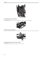
F-4-108
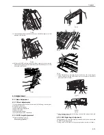
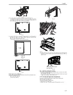
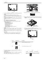
2) Mount the EEPROM removed in step 1) to the new ADF controller PCB.
MEMO:
The EEPROM on the new ADF controller PCB is not used yet.
3) Turn on the copier, and check to make sure that error code E420 is not in-
dicated.
4) If error code E420 is indicated, mount back the EERPOM once removed
from the new ADF controller PCB.
5) Perform the work under 1.2.3 "Adjusting the Sensors and the Delivery
Motor."
4.3.2.3 Adjusting the Sensors and the
0011-3501
Perform the adjustment if you have replaced any of the following parts:
- EEPROM (memory backup)
- Reversal sensor (S1)
- Pre-registration roller senor (S2)
- Post-registration roller sensor (S3)
- Separation paper sensor (S4)
- Skew paper sensor (S5)
- Original sensor (S6)
- Original trailing edge sensor (S7)
- Manual feed registration roller paper sensor (S9)
- Delivery motor (M5)
MEMO:
The delivery motor is adjusted by sending a reference signal to it, and the
speed of rotation at that time is measured by the delivery motor clock sensor
(PI11).
The result is used when generating the motor rotation speed control signal
(EJMPWM*).
Steps to Take
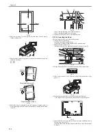
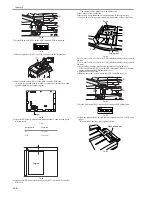
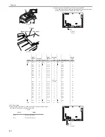
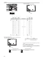
1) Open the DADF, and make a single A4 copy of a solid black original.
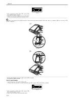
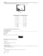
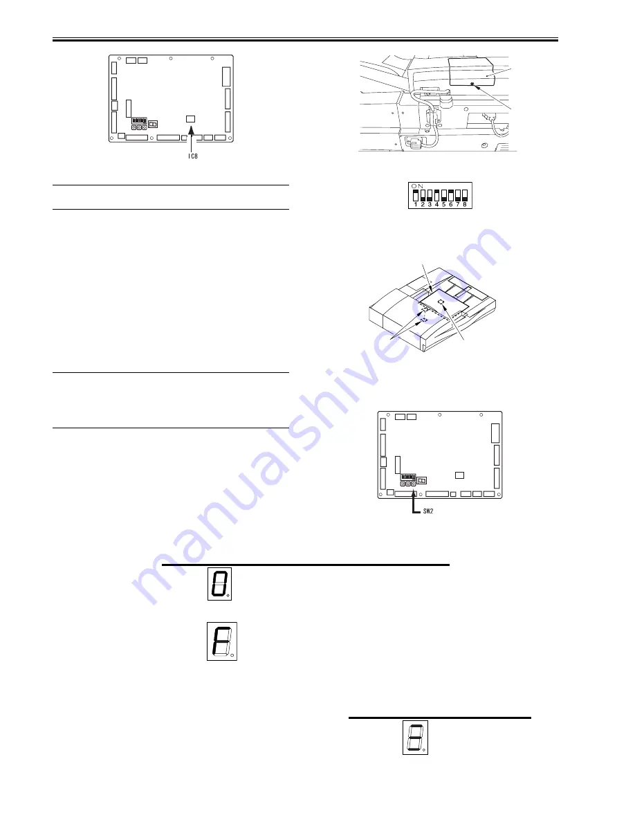
2) Remove the screw [1], and detach the ADF controller cover [2].
F-4-109
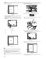
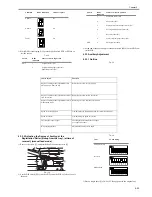
3) Set the DIP switch (SW1) on the ADF controller PCB as indicated.
F-4-110
4) Place the output obtained in step 1) in the original tray with the black side
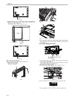
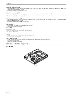
facing down. Take care not to cover the original sensor (S6) when placing
the output.
F-4-111
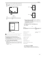
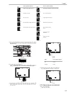
5) Press the push switch (SW2) on the ADF controller PCB.
- The LED will indicate the following in sequence, showing the result at
the end: 1, 2, 3, 4, 5, 6, 7, 8, 9, A.
F-4-112
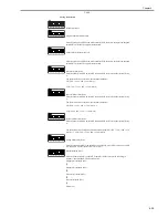
T-4-10
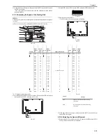
6) At the end of the operation, press the push switch (SW2) on the ADF con-
troller PCB once again.
If the Result is NG
Check the condition of each of the sensors (S1 through S9), and replace the
sensor considered to be faulty.
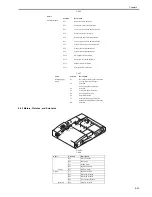
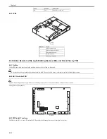
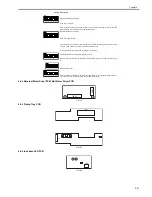
The condition of a sensor is indicated in the following three levels:
T-4-11
J1
J2
J5
J3
J6
J7
J8
J9
J10
J16
J15
J11
J14
IC8
J13
J12
J4
CB1
SW1
DSP1
SW4SW3SW2
[1]
[2]
Black side down
Original
sensor (S6)
Original trailing
edge paper sensor
(S7)
J1
J2
J5
J3
J6
J7
J8
J9
J10
J16
J15
J11
J14
IC8
J13
J12
J4
CB1
SW1
DSP1
SW4SW3SW2
Result
LED2 indication
Description
OK
(O)
All sensors (S1 through S9) are normal).
NG
(F)
Any of the sensors (S1 through S9) is faulty.
Condition
DSP1 indication
Check or replace
Good
No
Summary of Contents for DADF-Q1
Page 1: ...Aug 24 2007 Service Manual Feeder DADF Q1 ...
Page 2: ......
Page 6: ......
Page 11: ...Chapter 1 Specifications ...
Page 12: ......
Page 14: ......
Page 18: ......
Page 19: ...Chapter 2 Functions ...
Page 20: ......
Page 22: ......
Page 75: ...Chapter 3 Parts Replacement Procedure ...
Page 76: ......
Page 107: ...Chapter 4 Maintenance ...
Page 108: ......
Page 149: ...Chapter 5 Error Code ...
Page 150: ......
Page 152: ......
Page 154: ......
Page 155: ...Aug 24 2007 ...
Page 156: ......

