Chapter 4
4-25
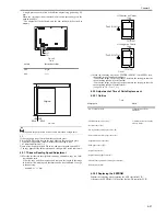
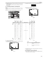
6) At the end of operation, press the push switch (SW2) on the ADF control-
ler PCB once again.
- The copy paper will be delivered, and the adjustment value will be
stored in memory.
4.3.3.3 Adjusting the Speed of the Feeding Belt
0011-3517
MEMO:
Adjusting the speed of the feeding belt will automatically adjust the speed of
reversal.
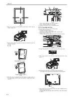
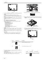
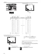
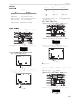
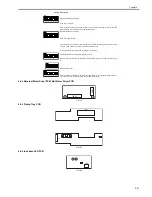
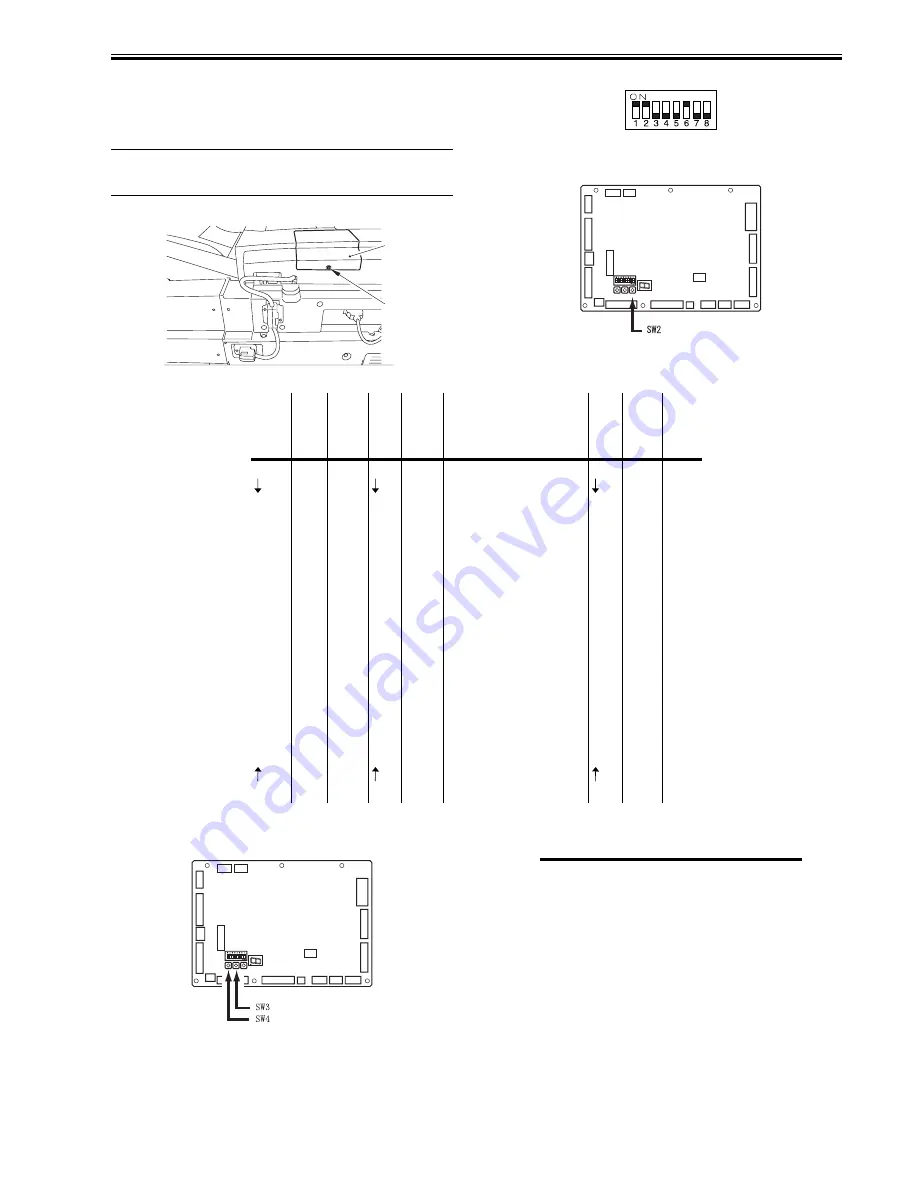
1) Remove the screw [1], and detach the ADF controller cover [2].
F-4-118
2) Set the DIP switch (SW1) on the ADF controller PCB as indicated.
F-4-119
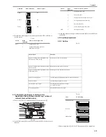
3) Pres the push switch (SW2).
- DSP 1 displays the current volume by flushing.
F-4-120
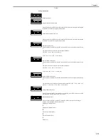
T-4-17
*0.1% (image reproduction ratio).
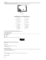
4) Press the push switch SW3 or SW4 on the ADF controller PCB, and adjust
the speed of the belt by referring to the table.
F-4-121
T-4-18
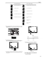
5) At the end of the operation, press the push switch (SW2) on the ADF con-
troller PCB once again.
4.3.3.4 Adjusting the Speed of Reversal
0011-3519
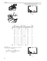
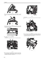
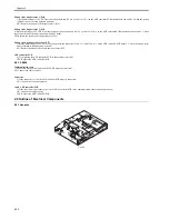
1) Remove the ADF cover [2] by the screw [1], and set the DIP switch (SW1)
on the ADF controller PCB as indicated.
[1]
[2]
J1
J2
J5
J3
J6
J7
J8
J9
J10
J16
J15
J11
J14
IC8
J13
J12
J4
CB1
SW1
DSP1
SW4SW3SW2
Switch
DSP1
indicat
ion
Adjust
ment
value*
Switc
h
DSP1
indicati
on
Adjustment value*
Switc
h
DSP1
indicati
on
Adjust
ment
value*
SW3
A-E2
-30
SW3
A-F7
-9
SW3
A-0C
12
A-E3
-29
A-F8
-8
A-CD
13
A-E4
-28
A-F9
-7
A-CE
14
A-E5
-27
A-FA
-6
A-CF
15
A-E6
-26
A-Fb
-5
A-10
16
A-E7
-25
A-FC
-4
A-11
17
A-E8
-24
A-Fd
-3
A-12
17
A-E9
-23
A-FE
-2
A-13
18
A-EA
-22
A-FF
-1
A-14
19
A-Eb
-21
A-00
0 (reference value)
A-15
20
A-Ec
-20
A-01
1
A-16
21
A-Ed
-19
A-02
2
A-17
22
A-Ee
-18
A-03
3
A-18
23
A-Ef
-17
A-04
4
A-19
24
A-F0
-16
A-05
5
A-1A
25
A-F1
-15
A-06
6
A-1b
26
A-F2
-14
A-07
7
A-1C
27
A-F3
-13
A-08
8
A-1d
28
A-F4
-12
A-09
9
A-1E
29
A-F5
-11
A-0A
10
A-1F
30
SW4
A-F6
-10
SW4
A-0b
11
SW4
-
-
J1
J2
J5
J3
J6
J7
J8
J9
J10
J16
J15
J11
J14
IC8
J13
J12
J4
CB1
SW1
DSP1
SW4SW3SW2
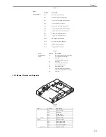
Switch
Change
SW3
Increases the belt speed (decreasing
the image).
SW4
Decreasing the belt speed (increasing
the image).
Summary of Contents for DADF-Q1
Page 1: ...Aug 24 2007 Service Manual Feeder DADF Q1 ...
Page 2: ......
Page 6: ......
Page 11: ...Chapter 1 Specifications ...
Page 12: ......
Page 14: ......
Page 18: ......
Page 19: ...Chapter 2 Functions ...
Page 20: ......
Page 22: ......
Page 75: ...Chapter 3 Parts Replacement Procedure ...
Page 76: ......
Page 107: ...Chapter 4 Maintenance ...
Page 108: ......
Page 149: ...Chapter 5 Error Code ...
Page 150: ......
Page 152: ......
Page 154: ......
Page 155: ...Aug 24 2007 ...
Page 156: ......

