Chapter 2
2-20
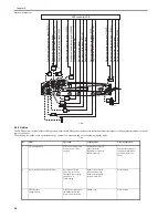
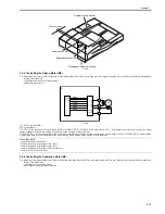
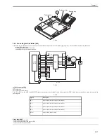
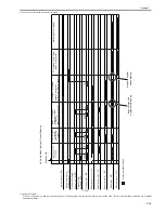
F-2-31
[1] ADF controller PCB
[2] Current detection circuit
M4: separation motor
MI2: separation motor clock sensor
When the CPU sends the motor rotation speed signal (SPPWM), the separation motor (M4) starts to rotate in a specific direction. The separation motor clock sensor
(PI2) sends the separation motor rotation speed signal (SPCLK) to IC17 (speed control IC). In response, IC17 compares the arriving rotation speed signal against
the speed reference signal (SEPCLKREF) from the CPU, and sends the result as the speed control signal (SPMFV) to the CPU. Using the arriving speed control
signal, the CPU varies the rotation speed signal. LED3 goes on when the motor rotation speed is within a specific range, while going off if out of the range. The
current detection circuit monitors the current flowing in the separation motor; when the level of the current exceeds a specific value, it sends the separation motor
stop signal (SPLIM) to stop the motor. The CPU identifies a fault in the separation motor if the separation motor stop signal continues, indicating an error code
(E405) on the host machine's display.
Error code: E405
- fault in the separation motor (M4)
- fault in the separation clock sensor (PI2)
- fault in the ADF controller PCB
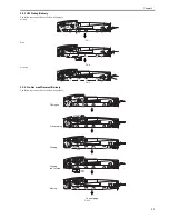
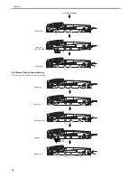
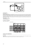
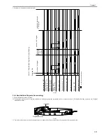
2.4.7 Sequence of Operations
0011-2347
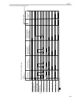
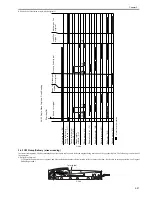
Picking Up/ Separation Originals
F-2-32
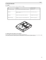
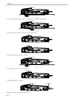
2.5 Document Feeding/Delivery
2.5.1 Outline
0011-2385
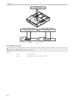
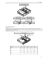
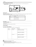
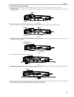
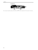
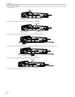
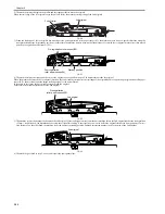
Originals are moved by rotating the feeding belt by the belt motor (M2). Further, originals are moved either to the right or to the left depending on the operating
mode in question.
Originals are delivered by rotating the delivery motor (M5). Originals are always delivered to the original delivery tray.
M4
SPLIM
SPPWM
SPCLK
SEPCLKREF
SPMFV
+24R
+5V
J12
J8
PI 2
IC18
CPU
Q28
Q29
LED3
IC16
1
2
5
Start key ON
Original sensor (S6)
Pickup roller home
position sensor (PI 7)
Pickup roller height
sensor 1/2 (PI 8/9)
Pickup motor (M3)
Separation motor (M4)
Separation clutch (CL)
Separation sensor (S4)
Skew sensor (S5)
UP
DOWN
UP
UP
DOWN
Picking up/
separating
1st original
Picking up/
separating
2nd original
End
Pickup roller shifting
to home position
Feeding/Separation
Pickup
position
Wait
position
Pickup
position
Wait
position
Home position
Summary of Contents for DADF-Q1
Page 1: ...Aug 24 2007 Service Manual Feeder DADF Q1 ...
Page 2: ......
Page 6: ......
Page 11: ...Chapter 1 Specifications ...
Page 12: ......
Page 14: ......
Page 18: ......
Page 19: ...Chapter 2 Functions ...
Page 20: ......
Page 22: ......
Page 75: ...Chapter 3 Parts Replacement Procedure ...
Page 76: ......
Page 107: ...Chapter 4 Maintenance ...
Page 108: ......
Page 149: ...Chapter 5 Error Code ...
Page 150: ......
Page 152: ......
Page 154: ......
Page 155: ...Aug 24 2007 ...
Page 156: ......

