Chapter 2
2-21
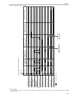
F-2-33
2.5.2 Controlling the Belt Motor (M2)
0011-2386
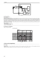
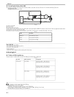
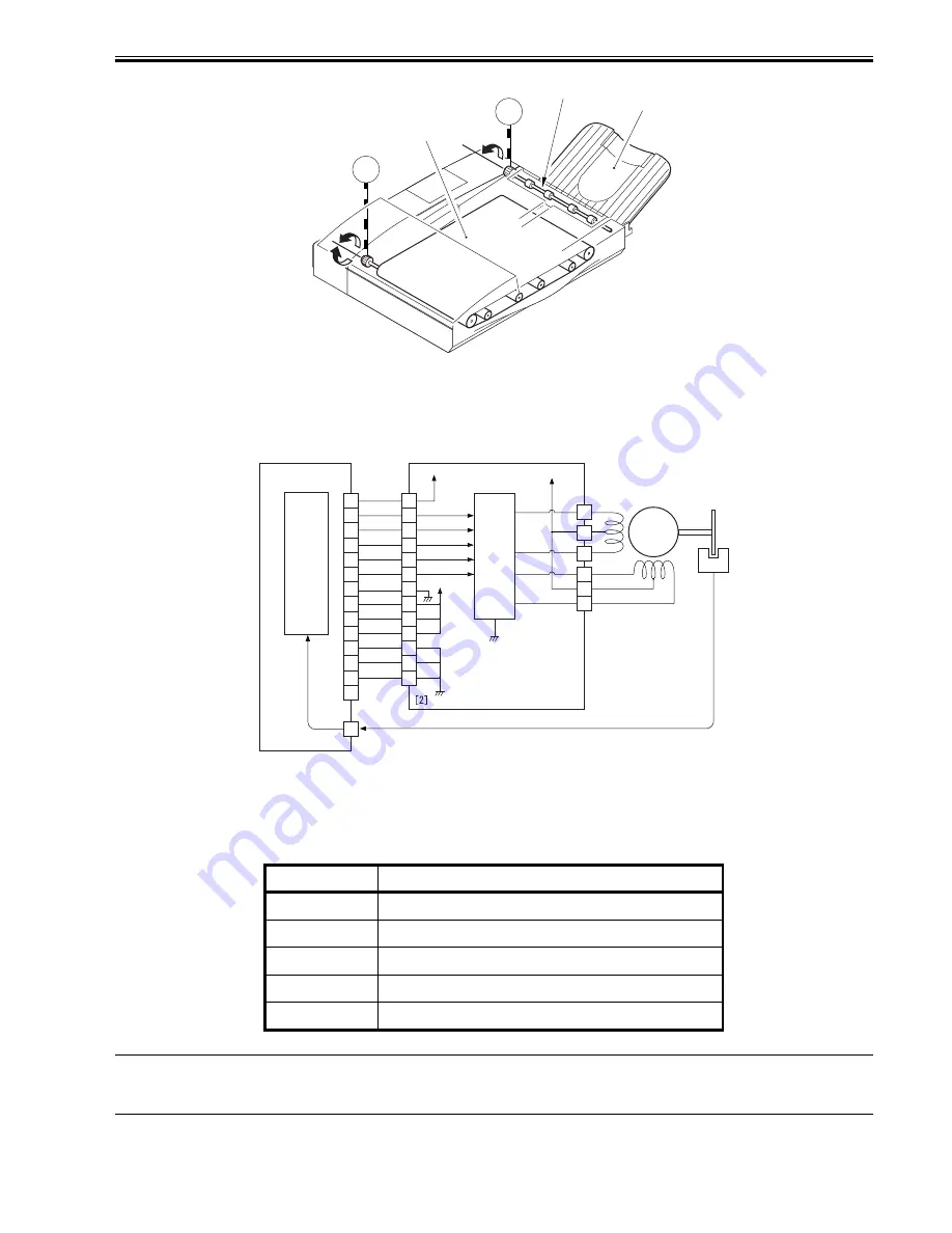
The following is a diagram of the circuit used to control the belt motor, which is a 4-phase stepping motor. The circuit has the following functions:
- turning off/on the motor
- controlling the direction of the motor
- controlling the speed of motor rotation
F-2-34
[1] ADF controller PCB
[2] belt motor driver PCB
M2: belt motor
PI1: belt motor clock sensor
The CPU (IC18) on the ADF controller PCB sends various motor control signals to the belt motor driver PCB, which in turn controls the motor as instructed by
these signals.
T-2-10
Error code: E402
- fault in the belt motor (M2)
- fault in the belt motor clock sensor (PI1)
- fault in the ADF controller PCB
Signals
Description
INA
phase control (direction and speed of rotation)
INB
phase control (direction and speed of rotation)
IN_A
phase control (direction and speed of rotation)
IN_B
phase control (direction and speed of rotation)
B-Vref
motor rotation torque setting
M5
M2
Delivery tray
Delivery roller
Feeding belt
IC18
CPU
Q601
+24U
+24R
A
A*
B
B*
M2
+5R
IN_B
IN_A
INB
INA
B-Vref
J602
J71
J7
PI 1
J12
BTCLK
13
12
11
10
9
8
7
6
5
4
3
2
1
1
2
3
4
5
6
7
8
9
10
11
12
13
14
3
3
1
4
6
2
5
[1]
Summary of Contents for DADF-Q1
Page 1: ...Aug 24 2007 Service Manual Feeder DADF Q1 ...
Page 2: ......
Page 6: ......
Page 11: ...Chapter 1 Specifications ...
Page 12: ......
Page 14: ......
Page 18: ......
Page 19: ...Chapter 2 Functions ...
Page 20: ......
Page 22: ......
Page 75: ...Chapter 3 Parts Replacement Procedure ...
Page 76: ......
Page 107: ...Chapter 4 Maintenance ...
Page 108: ......
Page 149: ...Chapter 5 Error Code ...
Page 150: ......
Page 152: ......
Page 154: ......
Page 155: ...Aug 24 2007 ...
Page 156: ......

