Chapter 4
4-29
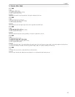
4.3.4 Other
4.3.4.1 Outline
0011-3589
T-4-23
4.3.4.2 Jam History
0011-3597
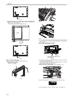
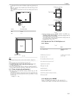
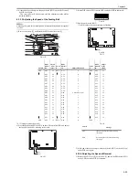
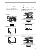
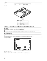
1) Remove the screw [1], and detach the ADF controller cover [2].
F-4-138
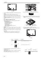
2) Set the DIP switch (SW1) on the ADF controller PCB as indicated.
F-4-139
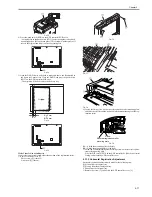
3) Press the push switch (SW2) on the ADF controller PCB.
- DSP1 will indicate the latest jam code.
F-4-140
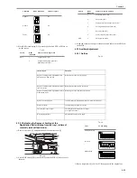
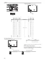
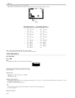
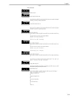
4) Press the push switches SW3 and SW4 to change the DSP1 indication,
thereby checking the jam history. DSP1 will flash five times in sequence
to indicate the nature of the jam.
F-4-141
T-4-24
5) At the end of the check, press the push switch (SW2) on the ADF control-
ler PCB once again.
4.3.4.3 Version of the Software
0011-3599
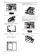
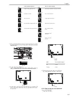
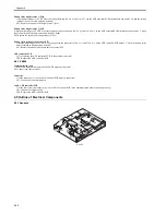
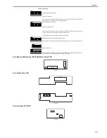
1) Remove the screw [1], and detach the ADF controller cover [2].
F-4-142
2) Set the DIP switch (SW1) on the ADF controller PCB as indicated.
F-4-143
3) Press the push switch (SW2) on the ADF controller PCB.
- DSP1 will flash four times to indicate the version of the software.
F-4-144
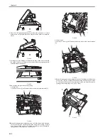
EX:
If for Version 3.01,
4) Press the push switch (SW2) on the ADF controller PCB to end the indi-
cation.
4.3.4.4 Checking the Original Width
0011-3606
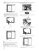
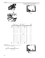
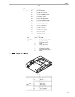
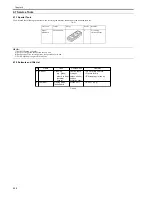
1) Remove the screw [1], and detach the ADF controller cover [2].
F-4-145
2) Set the DIP switch (SW1) on the ADF controller PCB as indicated.
F-4-146
Item
Description
Jam history
Indicates the most recent 3 jams.
Software version
Indicates the version of the software.
Document width detection
switch (SW301) check
A document width detection switch (SW301)
check is carried out automatically.
Backup RAM clearance
A backup RAM clear is performed.
[1]
[2]
J1
J2
J5
J3
J6
J7
J8
J9
J10
J16
J15
J11
J14
IC8
J13
J12
J4
CB1
SW1
DSP1
SW4SW3SW2
J1
J2
J5
J3
J6
J7
J8
J9
J10
J16
J15
J11
J14
IC8
J13
J12
J4
CB1
SW1
DSP1
SW4SW3SW2
Switch
DSP1
Description
SW3
1-X1-X2-Y1-Y2
Previous (latest)
2-X1-X2-Y1-Y2
2nd most recent
SW4
3-X1-X2-Y1-Y2
3rd most recent
[1]
[2]
J1
J2
J5
J3
J6
J7
J8
J9
J10
J16
J15
J11
J14
IC8
J13
J12
J4
CB1
SW1
DSP1
SW4SW3SW2
[1]
[2]
Summary of Contents for DADF-Q1
Page 1: ...Aug 24 2007 Service Manual Feeder DADF Q1 ...
Page 2: ......
Page 6: ......
Page 11: ...Chapter 1 Specifications ...
Page 12: ......
Page 14: ......
Page 18: ......
Page 19: ...Chapter 2 Functions ...
Page 20: ......
Page 22: ......
Page 75: ...Chapter 3 Parts Replacement Procedure ...
Page 76: ......
Page 107: ...Chapter 4 Maintenance ...
Page 108: ......
Page 149: ...Chapter 5 Error Code ...
Page 150: ......
Page 152: ......
Page 154: ......
Page 155: ...Aug 24 2007 ...
Page 156: ......


