


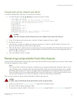


4. Remove the core routing blades (
on page 147).
5. Remove the control processor blades (
on page 162).
6. Remove the power supply assemblies or filler panels (
7. Remove the fan assemblies (
on page 193).
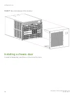
Installing the replacement chassis
Complete the following steps to install the replacement chassis.
DANGER
Use safe lifting practices when moving the product.
DANGER
A completely empty chassis weighs approximately 35.61 kg (78.5 lb) and requires a hydraulic or assisted lift to install it.
DANGER
A completely empty chassis weighs approximately 24.49 kg (54 lb) and requires a hydraulic or assisted lift to install it.
DANGER
Make sure the rack housing the device is adequately secured to prevent it from becoming unstable or falling over.
1. If the chassis is in a rack, remove it from the rack.
2. Place the chassis on a lift or on the shipping pallet provided with the original chassis and transport to storage location.
3. Unpack the new chassis.
a)
Cut the bands that encircle the packaging.
b) Open the top of the shipping box and remove accessory kit, rack mount kits, and foam from the top of the chassis.
c)
Lift the cardboard shipping container and inner cardboard sleeve off the chassis.
d) Remove the antistatic plastic off the chassis.
e)
Save the packing materials for use when returning the old chassis.
f)
Leave the chassis on top the foam shipping tray and wood pallet if the chassis must be transported to the installation
location.
g) Verify the contents of the shipping carton by referring to
h)
Save foam packing material and wooden pallet for reuse.
4. Use a pallet jack or other assisted lift to transport the new chassis to the installation area. Doorways must be wider than 91 cm
(36 in.) to accommodate the chassis on the pallet.
5. Use a lift to raise the chassis to the correct level. If installing the chassis in a rack, follow the instructions provided by the rack kit
manufacturer.
Installing components into the chassis
Follow electrostatic discharge (ESD) precautions when installing new components. Wear a wrist grounding strap connected to chassis
ground (if the device is plugged in) or a bench ground.
Installing the replacement chassis
Brocade X6-4 Director Hardware Installation Guide
218
53-1004106-07
Summary of Contents for X6-4
Page 12: ...Brocade X6 4 Director Hardware Installation Guide 12 53 1004106 07...
Page 20: ...Brocade X6 4 Director Hardware Installation Guide 20 53 1004106 07...
Page 28: ...Brocade X6 4 Director Hardware Installation Guide 28 53 1004106 07...
Page 64: ...Brocade X6 4 Director Hardware Installation Guide 64 53 1004106 07...
Page 86: ...Brocade X6 4 Director Hardware Installation Guide 86 53 1004106 07...
Page 102: ...Brocade X6 4 Director Hardware Installation Guide 102 53 1004106 07...
Page 130: ...Brocade X6 4 Director Hardware Installation Guide 130 53 1004106 07...
Page 140: ...Brocade X6 4 Director Hardware Installation Guide 140 53 1004106 07...
Page 166: ...Brocade X6 4 Director Hardware Installation Guide 166 53 1004106 07...
Page 196: ...Brocade X6 4 Director Hardware Installation Guide 196 53 1004106 07...
Page 200: ...Brocade X6 4 Director Hardware Installation Guide 200 53 1004106 07...
Page 204: ...Brocade X6 4 Director Hardware Installation Guide 204 53 1004106 07...
Page 210: ...Brocade X6 4 Director Hardware Installation Guide 210 53 1004106 07...
Page 224: ...Brocade X6 4 Director Hardware Installation Guide 224 53 1004106 07...
Page 238: ...Brocade X6 4 Director Hardware Installation Guide 238 53 1004106 07...