


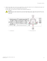


Connecting power cord to AC power supplies
Complete the following steps to connect the power cord from the facility AC power source to the device 's AC power supply. Before
connecting to power, be sure to observe all "Power Precautions" in
on page 21. In addition, refer to the power supply
specifications and requirements in
Brocade X6 Directors Technical Specifications
on page 225.
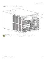
1. Remove the logo bezel protective cover if it is still installed over the top air vents on the port side of the chassis. Refer to
Removing logo bezel protective cover
on page 62 for instructions.
CAUTION
Remove the logo bezel protective cover on the port side of chassis before applying power. This cover is attached
over the air vents. If not removed, the chassis can overheat and will eventually shut down.
2. Install all power supplies provided for your device if not already installed. Refer to
on page 187 for
procedures.
3. When installing device in a rack, route power cables from power distribution units (PDUs) so they do not cover air vents in
chassis.
4. Connect the provided AC power cords to a power source with voltage of 200–240 VAC, 50/60 Hz or optionally to a power
source with voltage of 100–120 VAC, 50/60 Hz.
DANGER
High Touch Current. Earth connection essential before connecting supply.
NOTE
Use of the high-voltage line (200–240 VAC) is highly recommended because of better power-conversion efficiency.
With 120 VAC primary input, the power distribution unit (PDU) supplies roughly half the available wattage, which can
limit blade and port configurations. For a "fully-loaded" chassis with maximum supported blades and optics, two
power supplies connected to 200–240 VAC are required for full N+N redundancy. For details on power supplies
required for operation and high availability, refer to "Power supply requirements" and "Power consumption" tables in
the
Brocade X6 Directors Technical Specifications
5. Route the cords so they will be out of the way when connected to the power source. Ensure that the power cords have a
minimum service loop of 15.2 cm (6 in.) available and are routed to avoid stress.
6. Plug the power cords into power supplies. The power supply LED will light green when power is applied. Note that after one
power supply is plugged into AC power, LEDs on the remaining installed power supplies will flash green until they also have
power applied.
The director performs a power-on self-test (POST) each time it is powered on. POST takes approximately 10 minutes, during
which time status LEDs on installed blades and other FRUs may display amber. Power LEDs on all FRUs display green when
power-on self-test (POST) is complete and all FRUs are functional. You can bypass POST by using the
fastBoot
command.
You can also disable POST for successive reboots using the
diagDisablePost
command.
NOTE
Do not connect the device to the network until the IP addresses are
configured.
7. After POST is complete, verify that the power LEDs on blades and other FRUs are green.
For information about LED patterns, refer to
Monitoring the Device
.
8. Ground the chassis by attaching a ground wire from building ground to an appropriate crimp connector and attaching the
connector to the 2AWG Panduit LCD2-14AF lug located to the left of the bottom fan assembly near the bottom of the chassis.
Providing power to the device
Brocade X6-4 Director Hardware Installation Guide
53-1004106-07
67
Summary of Contents for X6-4
Page 12: ...Brocade X6 4 Director Hardware Installation Guide 12 53 1004106 07...
Page 20: ...Brocade X6 4 Director Hardware Installation Guide 20 53 1004106 07...
Page 28: ...Brocade X6 4 Director Hardware Installation Guide 28 53 1004106 07...
Page 64: ...Brocade X6 4 Director Hardware Installation Guide 64 53 1004106 07...
Page 86: ...Brocade X6 4 Director Hardware Installation Guide 86 53 1004106 07...
Page 102: ...Brocade X6 4 Director Hardware Installation Guide 102 53 1004106 07...
Page 130: ...Brocade X6 4 Director Hardware Installation Guide 130 53 1004106 07...
Page 140: ...Brocade X6 4 Director Hardware Installation Guide 140 53 1004106 07...
Page 166: ...Brocade X6 4 Director Hardware Installation Guide 166 53 1004106 07...
Page 196: ...Brocade X6 4 Director Hardware Installation Guide 196 53 1004106 07...
Page 200: ...Brocade X6 4 Director Hardware Installation Guide 200 53 1004106 07...
Page 204: ...Brocade X6 4 Director Hardware Installation Guide 204 53 1004106 07...
Page 210: ...Brocade X6 4 Director Hardware Installation Guide 210 53 1004106 07...
Page 224: ...Brocade X6 4 Director Hardware Installation Guide 224 53 1004106 07...
Page 238: ...Brocade X6 4 Director Hardware Installation Guide 238 53 1004106 07...