


connectivity to a patch panel or female terminated MTP patch cable to achieve up to 2 km distances. Refer to
on page 91 for more information.
•
Brocade supports fully populating a switch with ICL connections using a mixture of 50 and 100 m SWL optics and 16 Gbps 2
km LWL optics.
•
Any number of ICL ports can be used for 2 km distances when using 2 km LWL 16 Gbps QSFPs and configuring 20 buffer
credits per virtual channel. There are no limitations on the number of ICL ports if all ICL distances are a few hundred meters.
On the core routing blade faceplates, QSFP ports belonging to the same trunking groups are indicated with the same color border under
the ports. These colors are also applied to the port map labels on each blade faceplate to indicate ports belonging to the same trunking
groups.
For details on the following subjects, refer to the "Inter-Chassis Links' section of the
Brocade Fabric OS Administration Guide
:
•
ICL topologies
•
ICL trunking
•
Configuring ICLs between Brocade X6 Directors
•
Configuring ICLs between Brocade X6 and DCX 8510 Directors
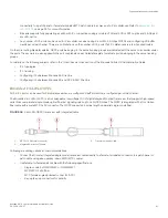
Brocade 2 km LWL QSFPs
All 16 ICL ports can be used for 2km distances when we configure 20 buffer credits are configured per virtual channel.
The Brocade 2 km LWL QSFP, is a hot-swappable, low-voltage (3.3 V) digital diagnostic optical transceiver that supports high-speed
serial links over parallel single-mode optical fibers at signaling rates up to 4×14.025 Gbps. The QSFP is integrated with a 3 m ribbon
fiber cable with a male MTP 1x12 connector. The QSFP supports 2 km link length on parallel single-mode fiber.
FIGURE 34
2 km LWL QSFP transceiver with integrated cable
1.
MTP 1x12 fiber male connector
2.
Integrated 3-meter MTP cable
3.
Transceiver with pull-tab
Following are cabling options and recommendations:
•
Connect the 3-meter integrated single mode transceiver cable directly to a female-terminated connector in a patch panel or
patch cable using a key-up/key-down MPO/MTP coupler.
•
Use female-to-female patch cable with the following specifications:
–
Single-mode (not OM3 MMF or OMM MMF)
–
MTP/MPO 1x12 fiber
–
MTP female angled polished connector (APC)
–
Key-up/key-up connectors for polarity
Supported transceivers and cables
Brocade X6-4 Director Hardware Installation Guide
53-1004106-07
91
Summary of Contents for X6-4
Page 12: ...Brocade X6 4 Director Hardware Installation Guide 12 53 1004106 07...
Page 20: ...Brocade X6 4 Director Hardware Installation Guide 20 53 1004106 07...
Page 28: ...Brocade X6 4 Director Hardware Installation Guide 28 53 1004106 07...
Page 64: ...Brocade X6 4 Director Hardware Installation Guide 64 53 1004106 07...
Page 86: ...Brocade X6 4 Director Hardware Installation Guide 86 53 1004106 07...
Page 102: ...Brocade X6 4 Director Hardware Installation Guide 102 53 1004106 07...
Page 130: ...Brocade X6 4 Director Hardware Installation Guide 130 53 1004106 07...
Page 140: ...Brocade X6 4 Director Hardware Installation Guide 140 53 1004106 07...
Page 166: ...Brocade X6 4 Director Hardware Installation Guide 166 53 1004106 07...
Page 196: ...Brocade X6 4 Director Hardware Installation Guide 196 53 1004106 07...
Page 200: ...Brocade X6 4 Director Hardware Installation Guide 200 53 1004106 07...
Page 204: ...Brocade X6 4 Director Hardware Installation Guide 204 53 1004106 07...
Page 210: ...Brocade X6 4 Director Hardware Installation Guide 210 53 1004106 07...
Page 224: ...Brocade X6 4 Director Hardware Installation Guide 224 53 1004106 07...
Page 238: ...Brocade X6 4 Director Hardware Installation Guide 238 53 1004106 07...