


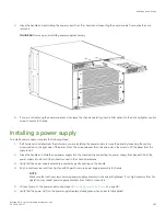


5. Install replacement WWN card assemblies into the empty slot using the following steps:
a)
Holding the card assembly by its edges with both hands along its length, slide it into the device slot.
b) Push with your thumb on the end of assembly to fully seat into the backplane connector.
c)
Use a #1 Phillips screwdriver to tighten the captive screw and secure the card assembly to the chassis.
NOTE
Be sure that captive screws are tightened. If not, high pressure from fan operation may unseat cards from chassis
connectors.
6. Power on the device and wait for five minutes for the device to boot.
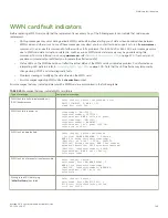
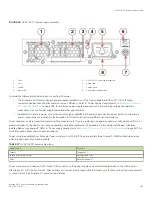
7. Verify that new WWN cards are correctly connected by checking LED function. For details on LED operation, refer to
on page 109.
NOTE
The LEDs may take up to two minutes after WWN card installation to begin functioning.
8. Resolve any issues flagged by RASlog EM-1220 and EM-1222 messages that display for the new card(s) before proceeding.
NOTE
Issues relating to data recovery on new WWN cards must be resolved at this point before proceeding to avoid invalid
WWN data, errors, and operating problems.
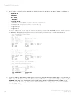
9. Determine the active CP blade by entering the
haShow
command.
10. On the active CP blade, run the
wwnrecover
command and specify WWN 2 card for recovery when prompted in
wwnrecover
output messages. Refer to
on page 171 for more information on this command.
11. If
wwnrecover
messages prompt for a system reboot, reboot both CP blades to ensure the system is running with valid WWN
card data.
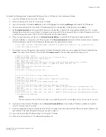
12. Verify the new card settings by running the following commands and comparing the output with the original
supportsave
data:
•
licenseidshow
•
ipaddrshow
•
switchname
•
chassisname
•
wwncardshow ipdata
•
chassisshow
(look at the WWN and chassis information at the bottom)
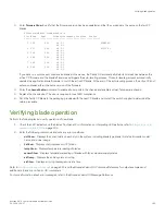
13. Run the
switchcfgpersistentenable
command to persistently enable each logical switch, that was disabled before removing the
WWN card(s):
switch:FID128:root> switchcfgpersistentenable
Switch's persistent state set to 'enabled'
14. Install the WWN bezel on the chassis.
a)
Orient the bezel on the chassis.
b) Insert and tighten both screws using a Phillips screwdriver.
15. Pack faulty WWN card assemblies in the packaging provided with the replacement cards, and return them to Brocade Support
for failure analysis (FA).
Cold-swap replacement
Brocade X6-4 Director Hardware Installation Guide
53-1004106-07
175
Summary of Contents for X6-4
Page 12: ...Brocade X6 4 Director Hardware Installation Guide 12 53 1004106 07...
Page 20: ...Brocade X6 4 Director Hardware Installation Guide 20 53 1004106 07...
Page 28: ...Brocade X6 4 Director Hardware Installation Guide 28 53 1004106 07...
Page 64: ...Brocade X6 4 Director Hardware Installation Guide 64 53 1004106 07...
Page 86: ...Brocade X6 4 Director Hardware Installation Guide 86 53 1004106 07...
Page 102: ...Brocade X6 4 Director Hardware Installation Guide 102 53 1004106 07...
Page 130: ...Brocade X6 4 Director Hardware Installation Guide 130 53 1004106 07...
Page 140: ...Brocade X6 4 Director Hardware Installation Guide 140 53 1004106 07...
Page 166: ...Brocade X6 4 Director Hardware Installation Guide 166 53 1004106 07...
Page 196: ...Brocade X6 4 Director Hardware Installation Guide 196 53 1004106 07...
Page 200: ...Brocade X6 4 Director Hardware Installation Guide 200 53 1004106 07...
Page 204: ...Brocade X6 4 Director Hardware Installation Guide 204 53 1004106 07...
Page 210: ...Brocade X6 4 Director Hardware Installation Guide 210 53 1004106 07...
Page 224: ...Brocade X6 4 Director Hardware Installation Guide 224 53 1004106 07...
Page 238: ...Brocade X6 4 Director Hardware Installation Guide 238 53 1004106 07...