


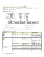

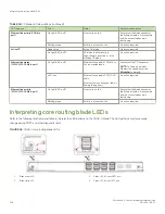


FIGURE 45
Control processor blade (CPX6)
1.
Blade status LED
2.
Blade power LED
3.
Chassis beacon LED
4.
Active (blue) CP LED
5.
10/100/1000 Mb/s Ethernet port (MGMT) link status LED
6.
10/100/1000 Mb/s Ethernet port (MGMT) link activity LED
7.
10/100/1000 Mb/s Ethernet port (SERVICE) link status LED
8.
10/100/1000 Mb/s Ethernet port (SERVICE) link activity LED
NOTE
The 10 Gbps Base-T RJ45 Ethernet port, shown to the right of the chassis beacon LED, is reserved for future use.
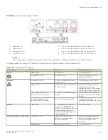
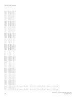
The following table describes the CP blade LED patterns and the recommended actions for those patterns.
TABLE 18
CP blade LED descriptions
LED purpose
Color
Status
Recommended action
Power
Steady green
CP blade is on.
No action required.
No light (LED is off)
CP blade is not on.
Ensure that the blade is firmly
seated and has power.
Attention
No light (LED is off)
CP blade is either healthy or does
not have power.
Verify that the power LED is on.
Steady amber
If on for more than 5 seconds, the
CP blade is faulty.
Ensure that the blade is firmly
seated and the switch has
completed booting. If LED remains
amber, consult the device supplier.
Slow-flashing amber (on 2
seconds, then off 2 seconds)
CP blade is not seated correctly or
is faulty.
Pull the blade out and reseat it. If
the LED continues to flash, replace
the blade.
Fast-flashing amber (on 1/2
second, then off 1/2 second)
Environmental range exceeded.
Check for out-of-bounds
environmental condition and correct
it.
Beacon
Steady white
LED illuminates white on both CP
blades when
chassisbeacon 1
is
issued from management interface
to locate chassis in equipment
racks. To turn off beaconing, issue
the
chassisbeacon 0
.
No action required.
Ethernet link status (10 Gb/s port)
No light (LED is off)
Either an Ethernet link is not
detected, or the blade does not
have incoming power.
Ensure that the blade has power,
the Ethernet cable is firmly seated,
and the connected device is
functioning.
Blinking green
Activity is present on link.
No action required.
Interpreting control processor blade LEDs
Brocade X6-4 Director Hardware Installation Guide
53-1004106-07
107
Summary of Contents for X6-4
Page 12: ...Brocade X6 4 Director Hardware Installation Guide 12 53 1004106 07...
Page 20: ...Brocade X6 4 Director Hardware Installation Guide 20 53 1004106 07...
Page 28: ...Brocade X6 4 Director Hardware Installation Guide 28 53 1004106 07...
Page 64: ...Brocade X6 4 Director Hardware Installation Guide 64 53 1004106 07...
Page 86: ...Brocade X6 4 Director Hardware Installation Guide 86 53 1004106 07...
Page 102: ...Brocade X6 4 Director Hardware Installation Guide 102 53 1004106 07...
Page 130: ...Brocade X6 4 Director Hardware Installation Guide 130 53 1004106 07...
Page 140: ...Brocade X6 4 Director Hardware Installation Guide 140 53 1004106 07...
Page 166: ...Brocade X6 4 Director Hardware Installation Guide 166 53 1004106 07...
Page 196: ...Brocade X6 4 Director Hardware Installation Guide 196 53 1004106 07...
Page 200: ...Brocade X6 4 Director Hardware Installation Guide 200 53 1004106 07...
Page 204: ...Brocade X6 4 Director Hardware Installation Guide 204 53 1004106 07...
Page 210: ...Brocade X6 4 Director Hardware Installation Guide 210 53 1004106 07...
Page 224: ...Brocade X6 4 Director Hardware Installation Guide 224 53 1004106 07...
Page 238: ...Brocade X6 4 Director Hardware Installation Guide 238 53 1004106 07...