


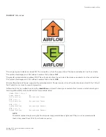


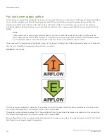


FIGURE 67
Airflow labels
The orange
I
symbol indicates an intake FRU. This unit pulls air in from the nonport side of the device and exhausts it out the port side.
This symbol should appear on FRUs with part numbers that contain an
NPI
.
The green
E
symbol indicates an exhaust FRU. This unit pulls air in from the port side of the device and exhausts it out the nonport side.
This symbol should appear on FRUs with part numbers that contain an
NPE
.
Ensure airflow direction of power supply and fan assemblies match. If power supply or fan air flow direction does not match, the FRU will
fault. Faulty fans can cause increase in temperature.
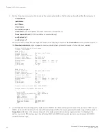
Airflow direction can be verified by entering the
chassisShow
command. Following is an example from command output indicating mis-
matching airflow. WWN units should indicate "Non-portside Intake".
POWER SUPPLY Unit: 1
Power Source: AC
Fan Direction: Non-portside Intake
...
FAN Unit: 2
Fan Direction: Non-portside Intake
...
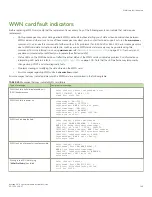
WWN Unit: 1
System AirFlow: Non-portside Exhaust
...
WWN Unit: 2
System AirFlow: Non-portside Exhaust
NOTE
Ensure that captive screws securing the fan and power supply assemblies are tightened. If they are not, air pressure inside
chassis may unseat these FRUs from chassis connectors.
Fan and power supply airflow
Brocade X6-4 Director Hardware Installation Guide
53-1004106-07
183
Summary of Contents for X6-4
Page 12: ...Brocade X6 4 Director Hardware Installation Guide 12 53 1004106 07...
Page 20: ...Brocade X6 4 Director Hardware Installation Guide 20 53 1004106 07...
Page 28: ...Brocade X6 4 Director Hardware Installation Guide 28 53 1004106 07...
Page 64: ...Brocade X6 4 Director Hardware Installation Guide 64 53 1004106 07...
Page 86: ...Brocade X6 4 Director Hardware Installation Guide 86 53 1004106 07...
Page 102: ...Brocade X6 4 Director Hardware Installation Guide 102 53 1004106 07...
Page 130: ...Brocade X6 4 Director Hardware Installation Guide 130 53 1004106 07...
Page 140: ...Brocade X6 4 Director Hardware Installation Guide 140 53 1004106 07...
Page 166: ...Brocade X6 4 Director Hardware Installation Guide 166 53 1004106 07...
Page 196: ...Brocade X6 4 Director Hardware Installation Guide 196 53 1004106 07...
Page 200: ...Brocade X6 4 Director Hardware Installation Guide 200 53 1004106 07...
Page 204: ...Brocade X6 4 Director Hardware Installation Guide 204 53 1004106 07...
Page 210: ...Brocade X6 4 Director Hardware Installation Guide 210 53 1004106 07...
Page 224: ...Brocade X6 4 Director Hardware Installation Guide 224 53 1004106 07...
Page 238: ...Brocade X6 4 Director Hardware Installation Guide 238 53 1004106 07...