
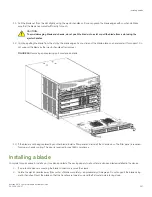


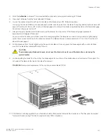


3. Follow these steps to insert the blade into the slot.
a)
Align the blade in the slot with the flat metal side of the blade at the bottom (blade power and status LEDs are on the left).
b) Carefully push the blade into the slot using your thumbs or fingers on the blade faceplate.
CAUTION
To avoid damaging blade and chassis, do not push the blade into a slot or pull the blade from a slot using the
ejector handles.
When the blade face is about 2.54 cm (1 in.) from the chassis, you should feel resistance as the blade connectors meet the
backplane connectors.
c)
Continue pushing with your thumbs or fingers until the ejectors move in towards the blade slightly indicating that the
connectors are engaged.
d) Simultaneously push both ejector handles in towards the blade center with even pressure until the blade completely seats in
the slot.
NOTE
As you move the handles, you will hear connectors engaging the backplane connector and possibly a slight
popping noise. This is normal and is due to the dense backplane.
4. Tighten the captive for each ejector using a #1 Phillips screwdriver.
As blade seats completely, amber blade status and green blade power LEDs illuminate.
NOTE
Be sure that captive screws are tightened. If not, high pressure from fan operation may unseat blade from chassis
connectors.
5. Observe the blade power and status LEDs and verify the following:
a)
Verify that the status LED on the blade shows amber until POST completes for the blade, then turns off. If the status LED
remains amber, the board may not be properly seated in the backplane or the board may be faulty.
NOTE
POST may take several minutes to complete on these blades.
b) Verify that the power LED on the port blade is displaying a steady green light to indicate that the blade has power. If it does
not turn on, ensure that the blade is firmly seated and ejector captive screws are tightened.
6. Install the transceivers and cables in the blade.
7. Group and route the cables through the vertical cable management finger assemblies.
8. Allow sufficient time for blade to initialize and for all ports to transition online.
9. Reinstall the chassis door. The door is required to meet EMI compliance.
Verifying blade operation
Perform the following tasks to verify operation of new blade:
1. Check the LED indicators on the blade's front panel. For information on interpreting LED patterns, refer to
on page 108.
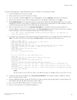
Enter the
slotShow
command and note any error conditions:
Verifying blade operation
Brocade X6-4 Director Hardware Installation Guide
53-1004106-07
149
Summary of Contents for X6-4
Page 12: ...Brocade X6 4 Director Hardware Installation Guide 12 53 1004106 07...
Page 20: ...Brocade X6 4 Director Hardware Installation Guide 20 53 1004106 07...
Page 28: ...Brocade X6 4 Director Hardware Installation Guide 28 53 1004106 07...
Page 64: ...Brocade X6 4 Director Hardware Installation Guide 64 53 1004106 07...
Page 86: ...Brocade X6 4 Director Hardware Installation Guide 86 53 1004106 07...
Page 102: ...Brocade X6 4 Director Hardware Installation Guide 102 53 1004106 07...
Page 130: ...Brocade X6 4 Director Hardware Installation Guide 130 53 1004106 07...
Page 140: ...Brocade X6 4 Director Hardware Installation Guide 140 53 1004106 07...
Page 166: ...Brocade X6 4 Director Hardware Installation Guide 166 53 1004106 07...
Page 196: ...Brocade X6 4 Director Hardware Installation Guide 196 53 1004106 07...
Page 200: ...Brocade X6 4 Director Hardware Installation Guide 200 53 1004106 07...
Page 204: ...Brocade X6 4 Director Hardware Installation Guide 204 53 1004106 07...
Page 210: ...Brocade X6 4 Director Hardware Installation Guide 210 53 1004106 07...
Page 224: ...Brocade X6 4 Director Hardware Installation Guide 224 53 1004106 07...
Page 238: ...Brocade X6 4 Director Hardware Installation Guide 238 53 1004106 07...