


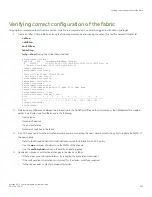


3. Enter the
slotShow -m
command and verify that all the installed cards are detected and that their status is operational (enabled).
switch:admin> slotShow -m
Slot Blade Type ID Model Name Status
--------------------------------------------------
1 CP BLADE 175 CPX6 ENABLED
2 CP BLADE 175 CPX6 ENABLED
3 SW BLADE 178 FC32-48 ENABLED
4 SW BLADE 178 FC32-48 ENABLED
5 CORE BLADE 176 CR32-4 ENABLED
6 CORE BLADE 176 CR32-4 ENABLED
7 SW BLADE 178 FC32-48 ENABLED
8 AP BLADE 186 SX6 ENABLED
4. Verify that the device is functioning correctly by entering
switchShow
or
switchStatusShow
.
This
switchShow
command displays the device and port status information.
switch0:admin> switchshow
switchName: sw0
switchType: 165.0
switchState: Online
switchMode: Native
switchRole: Principal
switchDomain: 130
switchId: fffc82
switchWwn: 10:00:00:05:31:03:2c:00
zoning: ON (ZONE_CONFIG_NAME)
switchBeacon: OFF
FC Router: OFF
HIF Mode: OFF
Allow XISL Use: OFF
LS Attributes: [FID: 128, Base Switch: No, Default Switch: Yes,
Address Mode 0]
Index Slot Port Address Media Speed State Proto
=======================================================
64 4 0 014000 -- N32 Online FC F-Port 10:00:00:05:1e:f8:a0:b4
65 4 1 014100 -- N32 Online FC F-Port 10:00:00:05:33:26:0e:65
66 4 2 014200 -- N32 Online FC F-Port 10:00:00:05:33:48:5e:f5
67 4 3 014300 -- N32 Online FC F-Port 10:00:00:05:1e:f8:a0:b3
68 4 4 014400 -- N32 Online FC F-Port 10:00:00:05:1e:f8:a0:b6
(output truncated)
5. Verify that all the IP address information is correct by entering
ipAddrShow
and checking the results against the IP information
recorded in the config-miscinfo.txt file.
switch:admin> ipaddrshow
SWITCH
Ethernet IP Address: xxx.xxx.xxx.12
Ethernet Subnetmask: 255.55.0.0
Fibre Channel IP Address: 1.2.3.4
Fibre Channel Subnetmask: 255.255.255.0
CP0
Ethernet IP Address: xxx.xxx.xxx.10
Ethernet Subnetmask: 255.55.0.0
HostName : cp0
Gateway Address: xxx.xxx.xxx.1
CP1
Ethernet IP Address: xxx.xxx.xxx.11
Ethernet Subnetmask: 255.55.0.0
HostName : cp1
Gateway Address: .1
Backplane IP address of CP0 : 10.0.0.4
Backplane IP address of CP1 : 10.0.0.5
switch:admin>switch:admin>
Verifying correct operation of system
Brocade X6-4 Director Hardware Installation Guide
222
53-1004106-07
Summary of Contents for X6-4
Page 12: ...Brocade X6 4 Director Hardware Installation Guide 12 53 1004106 07...
Page 20: ...Brocade X6 4 Director Hardware Installation Guide 20 53 1004106 07...
Page 28: ...Brocade X6 4 Director Hardware Installation Guide 28 53 1004106 07...
Page 64: ...Brocade X6 4 Director Hardware Installation Guide 64 53 1004106 07...
Page 86: ...Brocade X6 4 Director Hardware Installation Guide 86 53 1004106 07...
Page 102: ...Brocade X6 4 Director Hardware Installation Guide 102 53 1004106 07...
Page 130: ...Brocade X6 4 Director Hardware Installation Guide 130 53 1004106 07...
Page 140: ...Brocade X6 4 Director Hardware Installation Guide 140 53 1004106 07...
Page 166: ...Brocade X6 4 Director Hardware Installation Guide 166 53 1004106 07...
Page 196: ...Brocade X6 4 Director Hardware Installation Guide 196 53 1004106 07...
Page 200: ...Brocade X6 4 Director Hardware Installation Guide 200 53 1004106 07...
Page 204: ...Brocade X6 4 Director Hardware Installation Guide 204 53 1004106 07...
Page 210: ...Brocade X6 4 Director Hardware Installation Guide 210 53 1004106 07...
Page 224: ...Brocade X6 4 Director Hardware Installation Guide 224 53 1004106 07...
Page 238: ...Brocade X6 4 Director Hardware Installation Guide 238 53 1004106 07...