


CAUTION
If fan assembly LED operation indicates a fault or no power, verify that fan is fully seated in the chassis and that captive
screws securing fan in the chassis are fully tightened. If screws are loose, pressure from fans may unseat the fan from
chassis connectors.
Interpreting POST and boot results
The device performs Power-On Self-Test (POST) by default each time the device is powered on, rebooted, or reset. The device can be
rebooted using the
reboot
to reboot each CP individually) or
fastBoot
commands. The
fastBoot
command reboots the switches without
running POST. If the active CP blade is rebooted, it fails over to the standby CP blade.
POST
The device automatically performs POST each time it is powered on or reset.
To verify that POST has completed without error, do the following:
•
Verify that all LEDs return to a normal state after POST completes.
If one or more LEDs do not return to a normal state, and this is not due to the device being set to beacon, refer to the relevant
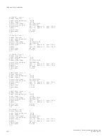
LED table to identify and correct the problem. For port blades, and CP and core switch blades, the
slotShow
command can be
used to check the status of the slots. For information about turning beaconing on or off, refer to the
Brocade Fabric OS
Administration Guide
.
•
Verify that the switch prompt displays when POST completes.
If it does not display, POST was not successfully completed. Contact the device supplier for support.
•
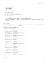
Review the system error log using the
errShow
or
errDump
commands.
Any errors detected during POST are written to the system log, which is accessible through the
errShow
command. For
information about error messages, refer to the
Brocade Fabric OS Message Reference
.
POST includes the following steps:
1. Preliminary POST diagnostics are run.
2. Operating system is initialized.
3. Hardware is initialized.
4. Diagnostic tests are run on several functions, including circuitry, port functionality, ability to send and receive frames, all aspects
of memory, parity, statistics counters, and serialization.
Boot
In addition to POST, boot includes the following steps after POST is complete:
1. Universal port configuration is performed.
2. Links are initialized.
3. Fabric is analyzed. If any ports are connected to other switches, the device participates in a fabric configuration.
4. The device obtains a domain ID and assigns port addresses.
5. Unicast routing tables are constructed.
6. Normal port operation is enabled.
Interpreting POST and boot results
Brocade X6-4 Director Hardware Installation Guide
114
53-1004106-07
Summary of Contents for X6-4
Page 12: ...Brocade X6 4 Director Hardware Installation Guide 12 53 1004106 07...
Page 20: ...Brocade X6 4 Director Hardware Installation Guide 20 53 1004106 07...
Page 28: ...Brocade X6 4 Director Hardware Installation Guide 28 53 1004106 07...
Page 64: ...Brocade X6 4 Director Hardware Installation Guide 64 53 1004106 07...
Page 86: ...Brocade X6 4 Director Hardware Installation Guide 86 53 1004106 07...
Page 102: ...Brocade X6 4 Director Hardware Installation Guide 102 53 1004106 07...
Page 130: ...Brocade X6 4 Director Hardware Installation Guide 130 53 1004106 07...
Page 140: ...Brocade X6 4 Director Hardware Installation Guide 140 53 1004106 07...
Page 166: ...Brocade X6 4 Director Hardware Installation Guide 166 53 1004106 07...
Page 196: ...Brocade X6 4 Director Hardware Installation Guide 196 53 1004106 07...
Page 200: ...Brocade X6 4 Director Hardware Installation Guide 200 53 1004106 07...
Page 204: ...Brocade X6 4 Director Hardware Installation Guide 204 53 1004106 07...
Page 210: ...Brocade X6 4 Director Hardware Installation Guide 210 53 1004106 07...
Page 224: ...Brocade X6 4 Director Hardware Installation Guide 224 53 1004106 07...
Page 238: ...Brocade X6 4 Director Hardware Installation Guide 238 53 1004106 07...