


9. General operation example
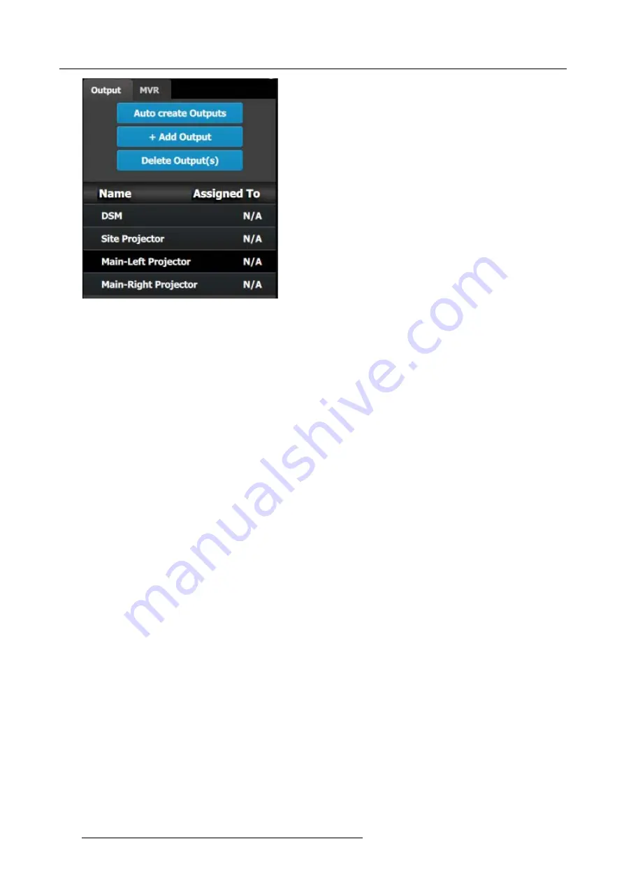
Image 9-8
Note:
The “N/A” at this end refers to the destinations that will be added next.
C5 – Part1: Add Site Screen Destinations
In this section we will create the Site Screen Destination and assign two layers.
1. Click on the
Destination
tab to de
fi
ne destinations for the created outputs.
2. From the diagram area click on the
fi
rst BNC of slot 13 that is the Site Projector output connector. The BNC will be highlighted.
3. Click on the
+Add Screen Destination
blue button to assign the output for the screen destination.
4. When the destination is created a box appears next to the E2 diagram.
5. Double click on the
Destination1
area in the Name list to edit the name.
6. When the area turns blue, click the eraser icon to clear the
fi
eld and type a new name, “Site Screen”.
7. Click on the top at the
Adjust:Site Screen
tab and in the
Assign
menu under the Output section click on the
+Assign Layer to
Destination
blue button to assign a layer to the destination .
8. In the layout area “1 layer” will appear in the green area of the box.
9. Repeat the previous step to add one more layer.
C5 – Part2: Add Main Screen Destinations
In this section we will create the Main Screen Destinations and assign 3 layers.
1. To create the Main Screen destination, please repeat steps 2 thru 6 of the previous stage (C5–Part1) by
fi
rst clicking on the
“Main-Left Projector” BNC.
2. Rename the destination to “Main Screen”.
3. After the destination is created, click on the “Main-Right Projector” BNC and drag it into the “Main Screen” destination box. The
Screen size will immediately change to 3840x1080.
4. Repeat the same steps as above to add layer to the destination but click the add button 3-times to add 3 layers.
C5 – Part3: adjust the projector overlap in Main Screen destinations
In this section we will adjust the projector overlap area for the Main screen.
1. Under the Wide menu in the small diagram area shows the destination, click on the line between the two sites. The line turns
blue.
2. Click on the
Data Double
button and enter “100” for the H overlap value. Note: We will leave the feathering to the default value
of 2.2.
268
R5905948 EVENT MASTER DEVICES 17/07/2017
Summary of Contents for S3 series
Page 1: ...Event Master Devices User s Guide R5905948 05 17 07 2017 ...
Page 9: ...Table of contents Index 531 R5905948 EVENT MASTER DEVICES 17 07 2017 5 ...
Page 10: ...Table of contents 6 R5905948 EVENT MASTER DEVICES 17 07 2017 ...
Page 20: ...2 Safety 16 R5905948 EVENT MASTER DEVICES 17 07 2017 ...
Page 66: ...4 Hardware orientation 62 R5905948 EVENT MASTER DEVICES 17 07 2017 ...
Page 90: ...5 Front Panel Menu orientation 86 R5905948 EVENT MASTER DEVICES 17 07 2017 ...
Page 264: ...8 Updating firmware 260 R5905948 EVENT MASTER DEVICES 17 07 2017 ...
Page 268: ...9 General operation example Image 9 3 264 R5905948 EVENT MASTER DEVICES 17 07 2017 ...
Page 285: ...9 General operation example Image 9 25 R5905948 EVENT MASTER DEVICES 17 07 2017 281 ...
Page 288: ...9 General operation example 284 R5905948 EVENT MASTER DEVICES 17 07 2017 ...
Page 316: ...10 Controller orientation 312 R5905948 EVENT MASTER DEVICES 17 07 2017 ...
Page 326: ...11 Controller Configuration 322 R5905948 EVENT MASTER DEVICES 17 07 2017 ...
Page 352: ...12 Controller Operation 348 R5905948 EVENT MASTER DEVICES 17 07 2017 ...
Page 418: ...13 E2 Maintenance 414 R5905948 EVENT MASTER DEVICES 17 07 2017 ...
Page 488: ...16 EC 200 Maintenance 484 R5905948 EVENT MASTER DEVICES 17 07 2017 ...
Page 494: ...17 Environmental information 490 R5905948 EVENT MASTER DEVICES 17 07 2017 ...
Page 512: ...A Specifications 508 R5905948 EVENT MASTER DEVICES 17 07 2017 ...
Page 527: ...C Troubleshooting C TROUBLESHOOTING R5905948 EVENT MASTER DEVICES 17 07 2017 523 ...
Page 528: ...C Troubleshooting 524 R5905948 EVENT MASTER DEVICES 17 07 2017 ...


