506
Maintenance / Servicing • Fan kit installation and replacement
Automation PC 620 with 945GME N270 CPU board User's Manual V 1.10
2.4 Procedure for APC620 with 5 PCI slot
•
Disconnect the power supply to the Automation PC 620.
•
Touch the housing or ground connection (not the power supply!) in order to discharge any
electrostatic charge from your body.
•
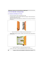
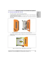
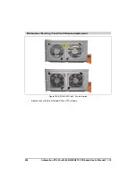
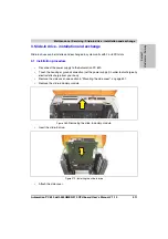
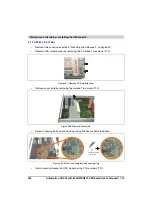
Open the orange front cover. Behind the cover there are 4 Torx screws (T10) that must
be removed.
•
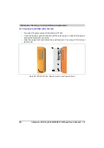
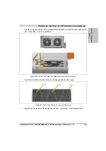
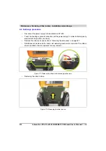
After the screws have been removed, the side cover and the fan kit cover can be removed
toward the front.
•
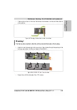
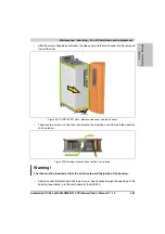
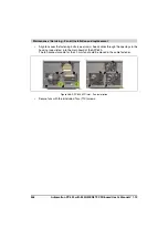
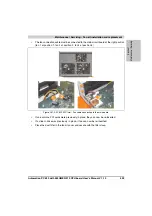
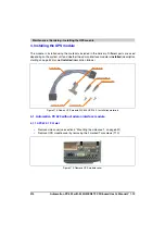
If one or more PCI cards are in place, they must be removed before moving on to the next
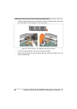
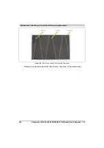
Figure 262: APC620 5PCI slot - Remove screws to install/ remove filter kit
Figure 263: APC620 5PCI slot - Remove side cover and fan kit cover
Side cover
Fan kit cover
Summary of Contents for Automation PC 620
Page 2: ...2 Automation PC 620 with 945GME N270 CPU board User s Manual V 1 10 ...
Page 4: ...4 Automation PC 620 with 945GME N270 CPU board User s Manual V 1 10 ...
Page 6: ...6 Automation PC 620 with 945GME N270 CPU board User s Manual V 1 10 ...
Page 568: ...568 Appendix A Glossary Automation PC 620 with 945GME N270 CPU board User s Manual V 1 10 ...

