574
Automation PC 620 with 945GME N270 CPU board User's Manual V 1.10
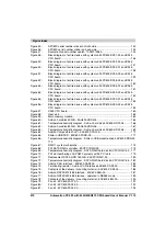
Figure index
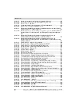
Firmware and software required for the UPS ............................................... 472
Add-on UPS module 5AC600.UPSI-00 ........................................................ 474
Add-on UPS module 5AC600.UPSI-00 - Installation materials .................... 475
Dimensions - 5AC600.UPSB-00 .................................................................. 478
PCI Ethernet card 10/100 - 5ACPCI.ETH1-01 ............................................. 483
Dimensions - 5ACPCI.ETH1-01 ................................................................... 484
PCI Ethernet card 10/100 - 5ACPCI.ETH3-01 ............................................. 485
Dimensions - 5ACPCI.ETH3-01 ................................................................... 486
B&R power supplies (examples) .................................................................. 491
APC620 1PCI slot - Remove screws to install/ remove filter kit ................... 496
APC620 1PCI slot - Remove side cover and fan kit cover ........................... 496
Markings for direction of airflow / fan rotation............................................... 497
APC620 1PCI slot - Fan cable connection to the main board ...................... 498
APC620 2PCI slots - Remove screws to install/ remove filter kit ................. 499
APC620 2PCI slots - Remove side cover and fan kit cover ......................... 499
Markings for direction of airflow / fan rotation............................................... 500
APC620 2PCI slots - Fan installation ........................................................... 500
APC620 2PCI slots - Fan cable connection to the main board .................... 501
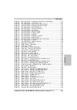
APC620 3PCI slot - Remove screws to install/ remove filter kit ................... 502
APC620 3PCI slots - Remove side cover and fan kit cover ......................... 503
Markings for direction of airflow / fan rotation............................................... 503
APC620 3PCI slot - Fan cable connection to the main board ...................... 505
APC620 5PCI slot - Remove screws to install/ remove filter kit ................... 506
APC620 5PCI slot - Remove side cover and fan kit cover ........................... 506
APC620 5PCI attach cable fasteners........................................................... 507
Markings for direction of airflow / fan rotation............................................... 507
Figure 266:
Summary of Contents for Automation PC 620
Page 2: ...2 Automation PC 620 with 945GME N270 CPU board User s Manual V 1 10 ...
Page 4: ...4 Automation PC 620 with 945GME N270 CPU board User s Manual V 1 10 ...
Page 6: ...6 Automation PC 620 with 945GME N270 CPU board User s Manual V 1 10 ...
Page 568: ...568 Appendix A Glossary Automation PC 620 with 945GME N270 CPU board User s Manual V 1 10 ...


