514
Maintenance / Servicing • Installing the UPS module
Automation PC 620 with 945GME N270 CPU board User's Manual V 1.10
4. Installing the UPS module
The module is installed using the materials included in the delivery. Different parts are used
depending on the system unit and whether the add-on interface module is
installed
(description
starting on page 523) or
not installed
(description follows).
4.1 Automation PC 620 without add-on interface module
4.1.1 APC620, 1 PCI slot
•
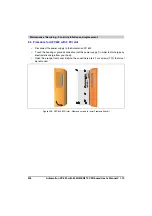
Remove side cover (see section 5 "Mounting the side cover", on page 531).
•
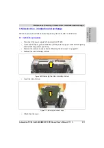
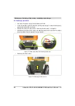
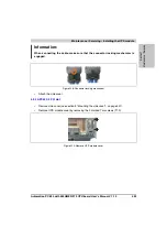
Remove UPS module cover by removing the 2 marked Torx screws (T10).
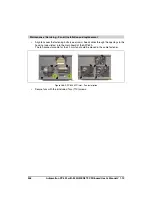
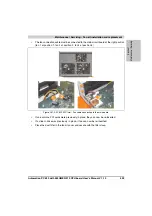
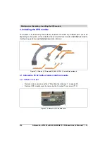
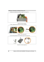
Figure 274: Add-on UPS module 5AC600.UPSI-00 - Installation materials
Figure 275: Remove UPS module cover
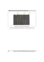
Connection cable
Mounting bracket
Spacing bolt (14 mm)
Spacing bolt (16 mm)
Torx screws (T10)
Spacing ring (2 mm)
Summary of Contents for Automation PC 620
Page 2: ...2 Automation PC 620 with 945GME N270 CPU board User s Manual V 1 10 ...
Page 4: ...4 Automation PC 620 with 945GME N270 CPU board User s Manual V 1 10 ...
Page 6: ...6 Automation PC 620 with 945GME N270 CPU board User s Manual V 1 10 ...
Page 568: ...568 Appendix A Glossary Automation PC 620 with 945GME N270 CPU board User s Manual V 1 10 ...


