Technical data • Entire device
Secti
on 2
Te
chn
ica
l da
ta
95
Automation PC 620 with 945GME N270 CPU board User's Manual V 1.10
2.10.4 Supply voltage for the 5PC600.SX05-00 (revision < H0) and 5PC600.SX05-01
(revision <= H0)
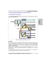
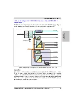
The following block diagram presents the simplified structure of the APC620 supply voltage for
system units 5PC600.SX05-00 (Revision < H0), 5PC600.SX05-01 (Revision < H0).
Explanation:
Systems with 5 PCI slots have two additional power supplies for the PCI bus and the slide-in
drives. The supply voltage is converted to 15 V with a DC/DC converter. These electrically
isolated 15 V feed four further DC/DC converters. Two ge12 V, and the others generate
3V3 and 5V standby. After the system is turned on (e.g. using the power button), the voltages
3V3, 5 V, +12 V are placed on the bus. At the 5 V output, yet another DC/DC converter
generates -12 V , and places these on the bus.
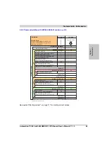
Figure 31: Supply voltage block diagram 5 PCI slots (dependent on system unit version)
24V
15V
Supply voltage
+24 VDC
Buffering capacitors
(for min. 10 ms)
3V3 Standby
3V3
3V3
5V
15V
+12V
+12V
5V
15V
Power On
15V
5V Standby
electrically
isolated
3V3 PCI bus
3V3
5V PCI bus and slide-in
+12V
+12V PCI bus
5V
5V
15V
15V
-12V
-12V PCI bus
PCI bus and slide-in power supply
UPS battery
Add-on UPS
module (optional)
Summary of Contents for Automation PC 620
Page 2: ...2 Automation PC 620 with 945GME N270 CPU board User s Manual V 1 10 ...
Page 4: ...4 Automation PC 620 with 945GME N270 CPU board User s Manual V 1 10 ...
Page 6: ...6 Automation PC 620 with 945GME N270 CPU board User s Manual V 1 10 ...
Page 568: ...568 Appendix A Glossary Automation PC 620 with 945GME N270 CPU board User s Manual V 1 10 ...


