Maintenance / Servicing • Installing the UPS module
Section 7
Ma
inte
nanc
e /
Servic
ing
525
Automation PC 620 with 945GME N270 CPU board User's Manual V 1.10
•
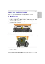
Attach the side cover.
4.2.2 APC620, 2 PCI slot
•
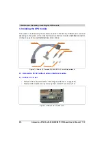
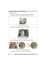
Remove side cover (see section 5 "Mounting the side cover", on page 531).
•
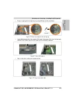
Remove UPS module cover by removing the 2 marked Torx screws (T10).
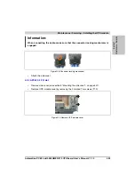
Information:
When connecting the cable, make sure that the connector locking mechanism is
engaged.
Figure 298: Connector locking mechanism
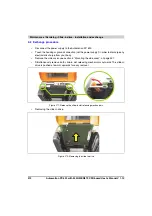
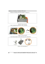
Figure 299: Remove UPS module cover
Summary of Contents for Automation PC 620
Page 2: ...2 Automation PC 620 with 945GME N270 CPU board User s Manual V 1 10 ...
Page 4: ...4 Automation PC 620 with 945GME N270 CPU board User s Manual V 1 10 ...
Page 6: ...6 Automation PC 620 with 945GME N270 CPU board User s Manual V 1 10 ...
Page 568: ...568 Appendix A Glossary Automation PC 620 with 945GME N270 CPU board User s Manual V 1 10 ...

