


4
Insert the attribute above the rectangle.
Notice that the Component type: Schematic Terminal dialog
box redisplays. The TAGSTRIP option is now grayed out since
that attribute has been placed for the symbol.
5
Select WIRENO, Height = 0.125 and Justify = Center.
6
Click Insert Attribute.
7
Insert the attribute above TAGSTRIP.
You do not have to insert the MFG, CAT or ASSYCODE attrib-
utes at this time since they are automatically added through
the Symbol Builder's WBLOCK option and set to invisible by
default.
8
Click Back to Main Menu.
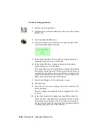
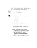
Add wire connection points
1
Click Wire Connection.
This allows you to define wire connection points and terminal
text for the library symbol. The Terminal style/configuration
dialog box displays.
You have to determine which direction the wire will attach to
the component. In this exercise, wire connection attributes
will be inserted at the left and right side of the symbol.
NOTE
Wire connection attributes should be on all 4 sides of a
terminal block so that it can be inserted in either horizontal or
vertical wires.
Build your own symbols | 1233
Summary of Contents for 22505-051400-9000 - AutoCAD Electrical 2008
Page 1: ...AutoCAD Electrical 2008 User s Guide February 20 2007 ...
Page 4: ...1 2 3 4 5 6 7 8 9 10 ...
Page 106: ...94 ...
Page 228: ...216 ...
Page 242: ...HP W TERM_ VDC SPECIAL SPACINGFACTOR 0 5 HP WA D TERM_ 02 230 Chapter 5 PLC ...
Page 294: ...282 ...
Page 564: ...552 ...
Page 698: ...686 ...
Page 740: ...728 ...
Page 814: ...802 ...
Page 1032: ...1020 ...
Page 1134: ...1122 ...
Page 1168: ...1156 ...
Page 1177: ...Insert P ID Component Overview of pneumatic tools 1165 ...
Page 1198: ...1186 ...
Page 1269: ...AutoCAD Electrical Command In this chapter AutoCAD Electrical Commands 20 1257 ...
Page 1304: ...Z zip utility 82 1292 Index ...