


you would have to modify the block file to add additional attributes such
as Line3.
Top terminals are the only symbols which can accept prompts during
the parametric PLC insertion process.
2
Edit each attribute value for the TAG attributes to read "IN-%%N."
Besides the Module Prompt variables, AutoCAD Electrical also supports
the use of an address variable. When the module is inserted, the PLC I/O
addresses are calculated based on some AutoCAD Electrical settings and
the module settings. You can trigger AutoCAD Electrical to include a
prefix or suffix to each address value it inserts.
The %%N represents the calculated I/O address and the IN- is the prefix
that gets added to the address value. You can also use the prompt values.
For example, if you want to permanently encode the rack and group
numbers (%%1 and %%2 prompts) into each I/O address value, encode
each I/O address entry in the date file with "TAGA_=%%1%%2%%N."
3
If you want to assign a text constant to any attribute value, combine a
text constant with the variables as shown in the module prompts and
addressing examples above.
Inserting the PLC module into the drawing
1
Click Save Module to save the module to the PLC database file.
2
Click Done/Insert.
The PLC Parametric Selection dialog box displays.
3
Click OK to insert the new PLC module onto the drawing.
4
Specify the insertion point on the drawing.
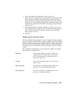
5
In the Module Layout dialog box, click OK.
6
In the I/O Address dialog box, specify a beginning I/O address or use the
quick picks to select an address (such as I:/00).
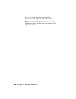
7
Click OK.
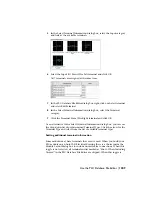
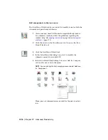
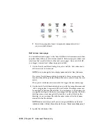
Your module should look similar to the following. The Manufacturer,
Catalog Number, and Description attributes also display at the top of the
module (not shown).
Use the PLC Database File Editor | 1213
Summary of Contents for 22505-051400-9000 - AutoCAD Electrical 2008
Page 1: ...AutoCAD Electrical 2008 User s Guide February 20 2007 ...
Page 4: ...1 2 3 4 5 6 7 8 9 10 ...
Page 106: ...94 ...
Page 228: ...216 ...
Page 242: ...HP W TERM_ VDC SPECIAL SPACINGFACTOR 0 5 HP WA D TERM_ 02 230 Chapter 5 PLC ...
Page 294: ...282 ...
Page 564: ...552 ...
Page 698: ...686 ...
Page 740: ...728 ...
Page 814: ...802 ...
Page 1032: ...1020 ...
Page 1134: ...1122 ...
Page 1168: ...1156 ...
Page 1177: ...Insert P ID Component Overview of pneumatic tools 1165 ...
Page 1198: ...1186 ...
Page 1269: ...AutoCAD Electrical Command In this chapter AutoCAD Electrical Commands 20 1257 ...
Page 1304: ...Z zip utility 82 1292 Index ...