Manual Weighing Controller A 810
Page
32
A.S.T. Angewandte SYSTEM-TECHNIK GmbH Dresden
A
D C
F T
5 0 0
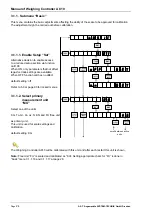
3.1.3. Submenu “ADC”
This menu is used to select the ADC and filter characteristics of the data acquisition. Analogue
parameters like gain and offset are preset during the production test procedure and need no further
adjustment.
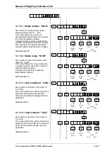
3.1.3.1. Filter component “FC”
Set in terms of number between 10 to
250 this value defines the number of
samples from the ADC to be used for
the continuously moving averaging filter
in connection with the ADC sampling
rate. Lower value provides faster stable.
default setting: 50
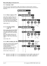
3.1.3.2. Threshold of filter
jump “FT”
Set in an range between 50 to 1000000
This value represents the ADC integer
value when the sliding filter is stopped
and restarted to trace any load change
directly.
This value should be slide above the
Maximum of interference caused by
vibrations. Higher value provides faster
stable.
default setting: 500
3.1.3.3. ADC sampling rate “SR”
Set in terms of preset values for standard
sampling rate and corresponds to the
number of samples per second
achieved by the ADC.
In connection to the filter settings the
system can be adjusted to the
application. Higher value is faster.
default setting: 50 samples / sec
Note: When SR = 100, “StAN” (3.1.1.11) is set automatically to 100 when “StAN” is greater than 100.
When SR = 200, “StAN” (3.1.1.11) is set automatically to 10 when “StAN” is greater than 10.
When SR = 400, “StAN” (3.1.1.11) is set automatically to 2 when “StAN” is greater than 2.
ENT
F C
0
/NET
GROSS
ENT
/NET
GROSS
0
FUNC
-1
+1
cursor
left
5 0
SHIFT
>
value
incr. decr.
cursor
right
TARE
0
/NET
GROSS
ENT
/NET
GROSS
0
FUNC
-1
+1
cursor
left
SHIFT
>
value
incr. decr.
cursor
right
TARE
S R
0
TARE
/NET
GROSS
ENT
/NET
GROSS
0
-1
+1
5 0
S R
Sampling rates
25; 50; 100;
200; 400
samples/sec
TARE
Summary of Contents for a810
Page 2: ......


