Amtech Axpert-Eazy AMT-011-4 Instruction Manual Download Page 8


Amtech


1.2 

1


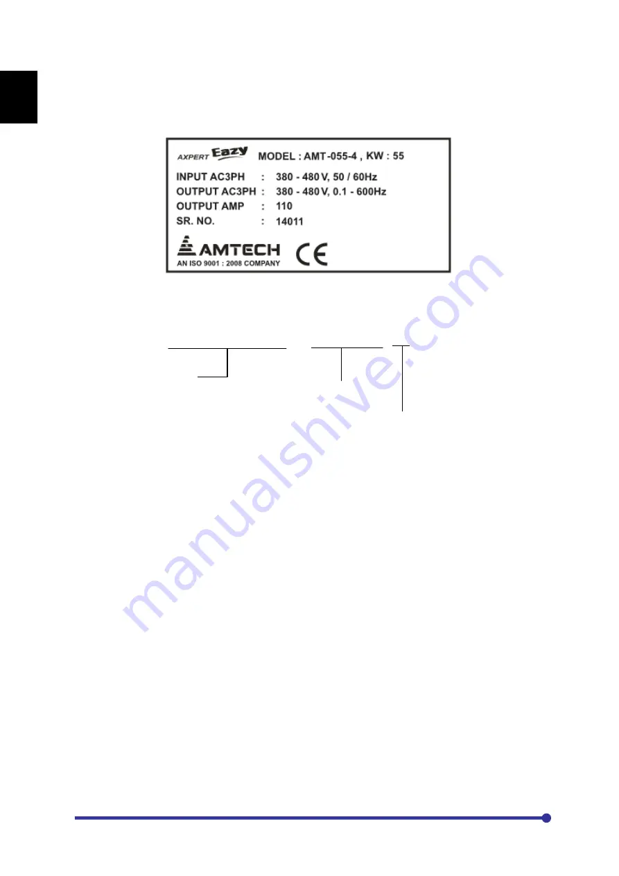
1-2 Details of rating nameplate and type display method 

The following details are listed on the rating nameplate. 


Using the above type as an example, the type is displayed as follows: 


AXPERT- EAZY

AMT - 055 - 4

Series name

Capacity 55kW

4: 380 ~ 480VAC, 3-phase, 50/60Hz
5: 500 ~ 575VAC, 3-phase, 50/60Hz

6: 600 ~ 690VAC, 3-phase, 50/60Hz

2: 200 ~ 240VAC, 3-phase, 50/60Hz

Summary of Contents for Axpert-Eazy AMT-011-4

Page 1: ...nce 2 Make sure that this manual is delivered to the final user 200 V System 11 kW 15 Hp 90 kW 125 Hp 400 V System 22 kW 30 Hp 1550 kW 2075 Hp 500 V System 30 kW 40 Hp 1550 kW 2075 Hp 600 V System 30...

Page 2: ...Amtech ii...

Page 3: ...OPERATION AND ADJUSTMENT 4 1 Preparation before turning power ON 4 2 Initialization of motor constants in Mode B 4 3 Automatic tuning adjustment CHAPTER 5 CONTROL INPUT OUTPUT TERMINALS 5 1 Input outp...

Page 4: ...encoder specifications 10 2 Wiring example CHAPTER 11 SERIAL COMMUNICATION SET UP 11 1 Connection method 11 2 Connecting the host computer and Axpert Eazy 1 to 1 11 3 Connecting the host computer and...

Page 5: ...IF THE FOLLOWING POINTS ARE NOT OBSERVED 1 DO NOT OPEN THE FRONT COVER WHILE THE POWER IS ON 2 A CHARGE STILL REMAINS IN THE AC DRIVE WHILE THE INDICATOR IS LIT EVEN IF THE POWER HAS BEEN TURNED OFF D...

Page 6: ...an understanding of the AC Drive A qualified person must do installation operation maintenance and inspection of this product Even qualified persons must undergo periodic training Qualified refers to...

Page 7: ...through rigorous quality control tests at the factory before shipment After receiving the AC drive check for the following 1 Check to make sure that the package includes an AC Variable Frequency Drive...

Page 8: ...ing details are listed on the rating nameplate Using the above type as an example the type is displayed as follows AXPERT EAZY AMT 055 4 Series name Capacity 55kW 4 380 480VAC 3 phase 50 60Hz 5 500 57...

Page 9: ...all and operate AC Drive that is damaged or that is missing parts Failure to observe this could lead to injuries Always observe the conditions described in the instruction manual for the installation...

Page 10: ...normal overheating Do not directly connect a resistor to the DC terminals L 1 L 2 and L Failure to observe this could lead to fires Tighten the terminal screws with the designated tightening torque Fa...

Page 11: ...ut output terminals The AC DRIVE input terminals are L1 L2 L3 The output terminals to the motor are U V W Connect the power supply to input terminals L1 L2 L3 only Never connect the power supply to th...

Page 12: ...120 x M10 11 0 0 43 28 3 1 11 19 0 75 11 0 0 43 M10 22 5 199 110 215 50 x 2p 1 0 x 2p 50 x M10 x 2p 11 0 0 43 18 5 0 73 30 1 18 11 0 0 43 M10 22 5 199 132 245 70 x 2p 2 0 x 2p 70 x M10 x 2p 11 0 0 43...

Page 13: ...0 11 0 0 43 18 5 0 73 19 0 75 10 5 0 41 M10 22 5 199 090 135 70 2 0 70 x M10 11 0 0 43 21 4 0 84 19 0 75 10 5 0 41 M10 22 5 199 110 150 90 3 0 90 x M10 11 0 0 43 25 5 1 0 19 0 75 10 5 0 41 M10 22 5 19...

Page 14: ...22 5 199 250 290 90 x 2p 3 0 x 2p 90 x M12 x 2p 13 0 0 51 25 5 1 0 40 1 58 38 1 50 13 0 0 51 M12 31 2 276 315 345 150 x 2p 250 kcmil x 2p 150 x M12 x 2p 13 0 0 51 31 0 1 22 40 1 58 38 1 50 13 0 0 51...

Page 15: ...ke a 360 high frequency grounding of cable entries in order to suppress electromagnetic disturbances In addition connect the cable shields to protective earth PE in order to meet safety regulations As...

Page 16: ...115V 115V 380V 460V 480V BLUE YELLOW BROWN VIOLET ORANGE BLACK BLUE GREEN RED WHITE RED RED BLACK 500V 600V Series 0V TR1 Fuse To L1 To L3 575V 550V 0V 0V 115V 115V 525V 600V 660V YELLOW WHITE BLACK...

Page 17: ...AMT 055 4 AMT 022 4 500V Series 500V Series AMT 037 5 AMT 045 5 AMT 055 5 AMT 011 5 AMT 015 5 AMT 018 5 600V Series AMT 022 5 AMT 030 5 AMT 045 6 AMT 055 6 AMT 075 6 600V Series AMT 011 6 AMT 015 6 A...

Page 18: ...Amtech 2 10 2 400V Series AMT 110 4 AMT 132 4 AMT 160 4 500V Series AMT 132 5 AMT 160 5 600V Series AMT 160 6 AMT 200 6...

Page 19: ...Axpert Eazy AC Variable Frequency Drive 2 11 2 400V Series AMT 200 4 AMT 250 4...

Page 20: ...Amtech 2 12 2 400V Series AMT 315 4 AMT 355 4 500V Series AMT 200 5 AMT 250 5 AMT 315 5 600V Series AMT 250 6 AMT 315 6 AMT 355 6...

Page 21: ...t can be changed between sink logic and source logic by changing the jumper position JP1 in PCA 2014A PCA 2004A between SINK and SOURCE position respectively Open cover designated as Control Unit to a...

Page 22: ...Amtech 2 14 2 This Page is intentionally left blank...

Page 23: ...de After the end of all modes it will carry the control again to first mode When changing the mode the last accessed parameter of last accessed group of successive mode will be displayed This key pass...

Page 24: ...keypad only When stop key is pressed for 2 5 seconds or longer during operation the drive will coast to stop regardless of Local or Terminal start control It is also used to reset the fault The stop k...

Page 25: ...ur user selectable parameters can be configured using A601 A604 3 1 Drive Status The fourth line of the Digital Operation Panel LCD Keypad Module is used to display different status of the unit as sho...

Page 26: ...ve Stop It shows that the AC Drive is in stop condition 18 Torque Mode It shows that the AC Drive is in Torque mode 19 Mains On It shows that the mains power supply is ON When first time MODE key is p...

Page 27: ...used to see the parameter value setting The parameter value except MODE M can be changed using ENTER GROUP UP DOWN keys For example the default local set frequency in A101 is 10 00 Hz To change the lo...

Page 28: ...t M o d e A G r o u p 1 A 1 0 1 L o c a l S e t F r e q 1 0 0 0 H z F w d L c l D r i v e S t o p Now press key once The value will be incremented by one M o d e A G r o u p 1 A 1 0 1 L o c a l S e t...

Page 29: ...mit function is activated Prepare a separate emergency stop switch in such cases Failure to do so could lead to injuries Resetting of a fault while the run signal is input could lead to restarting Alw...

Page 30: ...turning ON the power after completing wire 1 If problem can occur if the motor runs in reverse direction then remove the coupling and belt coupling the motor and machine so that the machine can be ru...

Page 31: ...speed response or torque response is required A401 4 8 4 1 2 Selection of start control The Axpert Eazy AC Drive can be controlled from various places like Digital Operation Panel Local Terminal or fr...

Page 32: ...211 When using the close loop vector control mode input the correct PPR for the encoder in B109 Refer Chapter 10 for the encoder specifications and wiring method Motor direction definition With the Ax...

Page 33: ...407 On On On On On Off Off Off Off Off Preset i p 2 PSI B402 B406 On Off RUN A104 Jog Select On Off On Off Ref Select 0 PSI Ref Select 1 PSI Serial FSI 4 20mA On Off Ref Select 1 PSI Static Pot A106 1...

Page 34: ...Set motor parameter in B102 B103 B104 B105 B106 B107 B109 if A401 2 4 6 8 2 A201 Acceleration time and A202 deceleration time should be 10 second or greater than 3 Set the automatic tuning mode in B20...

Page 35: ...ductance is adjusted in this mode however the motor will rotate to the maximum speed during automatic tuning so special attention must be paid to safety Abnormal completion of automatic tuning If auto...

Page 36: ...D direction in A305 Motor Direction and increase the frequency to 50Hz This completes the test operation with the operation panel After this carry out the parameter settings and adjust the load operat...

Page 37: ...Axpert Eazy AC Variable Frequency Drive 4 9 4...

Page 38: ...Amtech 4 10 4 This page is intentionally left blank...

Page 39: ...an be configured to different functions using C115 PSI1 6 Programmable Sequence Inputs 1 6 These are programmable sequence inputs and can be configured to different functions using C101 C106 PSO1 4 Pr...

Page 40: ...IO2 Different seven internal signals can be assigned to these outputs using C203 C204 IO2 Iout 2 TX DATA These two signals are for the two wire RS 485 serial link The protocol used is Modbus RTU RX DA...

Page 41: ...d with JP1 as shown in the above figure 5 3 Programmable analog input PAI wiring FSV P15 15V 940R 33k 10k 0V 2k 2W VIN L 30m 98 4 33k 10k 0V FSI 270R 0V 20mA IIN L 30m 98 4 270R 0V 20mA 10V Precaution...

Page 42: ...output current is 1mA for voltage output 3 Use a shielded wire shorter than 30meters 98 4 for the wiring 4 For the shield connections open the mate side and connect to 0V terminal on TB1 5 5 Programm...

Page 43: ...FB L 50m 164 R1C R1A R1B L 50m 164 PROGRAMMABLE FAULT RELAY PROGRAMMABLE RELAY1 PROGRAMMABLE RELAY2 Precautions 1 Use within the rated range shown below Rated capacity resistance load 250VAC 1A or 30...

Page 44: ...A ANALOG INPUT ANALOG OUTPUT SEQUENCE INPUT 5 6k Output Frequency Output Current Preset Input 0 Preset Input 1 Preset Input 2 Sink logic operation is considered for programmable sequence inputs in thi...

Page 45: ...AN 5V COM RS 485 TB1 PSO1 PSO2 PSO3 PSO4 COM R1B R2A R2C R2B TB2 FA FC FB R1A R1C NC Programmable Relay 2 Programmable Relay 1 Programmable Fult Relay Programmable Sequence Outputs Encoder Connections...

Page 46: ...Amtech 5 8 5 This page is intentionally left blank...

Page 47: ...e value of currently selected PID feedback in the unit selected in C614 M111 FSV Input Voltage V 0 1 Display the analog input voltage at FSV M112 FSI Input Current mA 0 1 Display the analog input curr...

Page 48: ...Automatic Tuning display The progression state of automatic tuning is displayed M304 Rated Current A 0 1 This indicates the rated current of the AC DRIVE M305 Inverter Type KW This indicates the AC DR...

Page 49: ...put Current V2 Amp 0 1 Display the Output Current of V2 phase of Inverter Unit 2 M607 Output Current W2 Amp 0 1 Display the Output Current of W2 phase of Inverter Unit 2 M608 Output Current2 Amp 0 1 D...

Page 50: ...ture Panel 2 o C 1 Actual Inside temperature of Panel 2 is displayed M710 Driver Status The ON OFF state of driver fault status from Inverter Unit IU is be displayed M711 Temperature IU 6 o C 1 Actual...

Page 51: ...O P 4 A107 Local Set Torque 0 0 200 0 200 0 0 1 This is set torque from the operation panel in vector control mode A108 Torque Reference Input 1 1 18 1 This is used to select the torque reference in...

Page 52: ...ion time related parameters A201 A207 and D206 D207 1 x1 2 x10 3 x100 GROUP 3 START STOP SELECTION DC BRAKING A301 Start Control 1 1 3 1 Select start location 1 Local 2 Terminal 3 Serial A302 Maintain...

Page 53: ...ormal duty Vector Control A402 V F Selection 1 1 3 1 Select the appropriate v f curve 1 Linear Curve 2 Square Curve 3 Custom setting A403 Base Frequency 100 0 5 0 100 0 0 1 This is output frequency at...

Page 54: ...110 Fb 8 M201 Vry 9 M202 Vyb A605 Norm Parameter 5 8 1 25 1 10 M203 Vo 11 M204 Vdc 12 M205 kW A606 Norm Parameter 6 11 1 25 1 13 M206 kWh 14 M207 MWh 15 M208 C A607 Norm Parameter 7 12 1 25 1 16 M211...

Page 55: ...in Max Res Description WP A706 Variable Bias 1 1 6 1 This parameter can be used to add variable bias into the output after the math operation Select the variable bias from the options given below 1 No...

Page 56: ...07 Motor Poles 4 2 16 2 Insert the motor poles B108 No Load Output Voltage Vac 160 20 480 1 The terminal voltage at no load at the base speed is set B109 Encoder Pulses P R 1024 60 10000 1 Set as per...

Page 57: ...n of the entered value for Secondary Rotor Resistance of motor B205 R2 Secondary Rotor Resistance Exponent 0 3 4 1 This is exponent section of the entered value for Secondary Rotor Resistance of motor...

Page 58: ...wise 0 Disable 1 Enable B309 Change Password 0 0 9999 1 User can change the 4 digit user password for parameter lock B310 Parameter Lock 0 0 9999 1 User selectable 4 digit password to prevent unintent...

Page 59: ...n of KEB PID controller B321 KEB Ti mS 500 0 1 0 5000 0 0 1 This parameter is used to set the integral time constant of KEB PID controller B322 KEB Td mS 0 5 0 0 500 0 0 1 This parameter is used to se...

Page 60: ...r higher frequency above B621 B611 Over Speed Protection Level 105 0 20 0 200 0 0 1 This is the over speed protection level When the detection speed is equal to or higher than the set level for 1000ms...

Page 61: ...fault B627 Field Weakening Gain 1 00 0 10 2 00 0 01 Field Weakening Gain If hunting occurred in speed in field weakening region decrease gain GROUP 7 VECTOR CONTROL CONSTANTS 2 B701 Torque Mode Select...

Page 62: ...00 0 01 This is the reference speed frequency for changing the compensation amount according to the operation speed This table value changes when maximum frequency A103 changes B802 Table Reference Sp...

Page 63: ...Speed Detect1 9 Acceleration 11 Aux Drive 13 Zero Speed 15 PID Up Limit 17 Temp Alarm 19 Pump 1 21 Pump 3 23 Doff End Alarm 25 Fault 27 PLC Output 2 29 PLC Output 4 31 PLC Output 6 33 PID F B ULmt 35...

Page 64: ...ting for analog output voltage VO1 C222 Vout 2 Bias 100 0 1000 1 This is bias setting for analog output voltage VO2 C223 Input voltage gain 1 000 0 100 2 000 0 001 This parameter sets the gain for VRY...

Page 65: ...d 2 Min frequency A102 3 Max frequency A103 4 A101 Set frequency 5 B401 Preset speed 1 C314 I Detection Hysteresis Level 5 1 20 1 This parameter sets the hysteresis level for I Detection operation C31...

Page 66: ...5 AUTO RESTART SPEED SEARCH FUNCTION C501 No Of Restart 0 0 10 1 Sets the number of restart for ten faults C502 Restart Wait Time Sec 5 1 30 1 Sets the wait time before auto restart C503 Emergency St...

Page 67: ...20mA 6 Serial 8 PLC A O P 2 10 PLC A O P 4 C604 PID Feedback Input Selection 3 1 8 1 Decides the feedback input point for the PID 1 FSV 0 10V 3 Vin 0 10V 5 PLC A O P 1 7 PLC A O P 3 2 FSI 4 20mA 4 Iin...

Page 68: ...ter output is switched OFF if the frequency reference or PID output remains below the sleep mode enter frequency for the set time period Sleep mode can be used with or without PID control 0 Disable 1...

Page 69: ...1 PLC panel parameter 5 6 are used in built PLC for Timer 3 application C706 PLC Panel Parameter 6 0 0 32767 1 C707 PLC Panel Parameter 7 0 0 32767 1 PLC panel parameter 7 8 are used in built PLC for...

Page 70: ...e for auxiliary drive 1 Local 3 FSI 4 20mA 5 FSI 0 20mA 7 FSI 20 4mA 9 FSI 20 0mA 11 Serial 13 VIN 0 10V 15 PLC A O P 1 17 PLC A O P 3 2 FSV 0 10V 4 FSV 0 5V 6 FSV 10 0V 8 FSV 5 0V 10 Static pot 12 PI...

Page 71: ...rrent value as a percentage of motor rated current for normal running condition The default value is 155 when heavy duty is set D402 Adjustable Over Current Level 300 50 300 1 Set the upper current li...

Page 72: ...01 Set frequency for Table 1 Step 3 E204 Freq T1 STP4 Hz 5 00 0 01 600 0 01 Set frequency for Table 1 Step 4 E205 Freq T1 STP5 Hz 5 00 0 01 600 0 01 Set frequency for Table 1 Step 5 E206 Freq T1 STP6...

Page 73: ...Freq T2 STP2 Hz 5 00 0 01 600 0 01 Set frequency for Table 2 Step 2 E403 Freq T2 STP3 Hz 5 00 0 01 600 0 01 Set frequency for Table 2 Step 3 E404 Freq T2 STP4 Hz 5 00 0 01 600 0 01 Set frequency for T...

Page 74: ...00 0 01 600 0 01 Set frequency for Table 3 Step 2 E603 Freq T3 STP3 Hz 5 00 0 01 600 0 01 Set frequency for Table 3 Step 3 E604 Freq T3 STP4 Hz 5 00 0 01 600 0 01 Set frequency for Table 3 Step 4 E60...

Page 75: ...ction E709 RSF Time T3 STP9 Sec 10 0 0 1 6000 0 0 1 Set time for Table 3 Step 9 for RSF function E710 RSF Time T3 STP10 Sec 10 0 0 1 6000 0 0 1 Set time for Table 3 Step 10 for RSF function E711 RSF T...

Page 76: ...G111 PR Mode T1 STP11 1 1 3 1 G112 PR Mode T1 STP12 1 1 3 1 G113 PR Mode T1 STP13 1 1 3 1 G114 PR Mode T1 STP14 1 1 3 1 G115 PR Mode T1 STP15 1 1 3 1 GROUP 2 MODE SELECTION FOR PATTERN RUN TABLE 2 G2...

Page 77: ...6000 0 0 1 Set time for Table 1 Step 14 for Pattern Run G315 PR Time T1 STP15 Sec 10 0 0 1 6000 0 0 1 Set time for Table 1 Step 15 for Pattern Run GROUP 4 PATTERN TIME FOR TABLE 2 G401 PR Time T2 STP1...

Page 78: ...Step T1 STP10 1 1 14 1 Set return step for Table 1 Step 10 G511 Return Step T1 STP11 1 1 14 1 Set return step for Table 1 Step 11 G512 Return Step T1 STP12 1 1 14 1 Set return step for Table 1 Step 12...

Page 79: ...p 9 G610 Return Step T2 STP10 1 1 14 1 Set return step for Table 2 Step 10 G611 Return Step T2 STP11 1 1 14 1 Set return step for Table 2 Step 11 G612 Return Step T2 STP12 1 1 14 1 Set return step for...

Page 80: ...the next pump will be switched ON H103 Pump Stop Hold Time Sec 60 0 0 1 3600 0 0 1 If the PID output reaches to lower limit and remains there for more than the set time the next pump will be switched...

Page 81: ...t 41 PLC Inst 50 0 0 1 In built PLC Command 41 50 GROUP 6 IN BUILT PLC COMMAND PARAMETERS P601 P610 PLC Inst 51 PLC Inst 60 0 0 1 In built PLC Command 51 60 GROUP 7 IN BUILT PLC COMMAND PARAMETERS P70...

Page 82: ...auxiliary drive When selected for the normal parameter display in A601 A608 the value will be displayed with Amp unit M104 Output Current It displays actual output current of AC DRIVE as a percentage...

Page 83: ...parameter displays the value of currently selected PID feedback input source in the unit selected in C614 When selected for the normal parameter display in A601 A608 the value will be displayed with F...

Page 84: ...s selected it displays the output voltage for the auxiliary drive When selected for the normal parameter display in A601 A608 the value will be displayed with Vo unit M204 DC Bus Voltage Vdc This para...

Page 85: ...Money Saved with VFD M216 Money Saved with VFD x1K This parameter displays the money saved using VFD This may differ from the actually saved money To get the nearest value enter the kW consumption in...

Page 86: ...al cumulative AC DRIVE run time after product shipment is counted and displayed in this parameter M303 Automatic Tuning display This parameter displays the progress of auto tuning process when auto tu...

Page 87: ...er displays the month of unit shipment M311 Ship Year This parameter displays the year of unit shipment M312 Display Version This parameter displays the ROM version of Display Board PCA 2012 of AC DRI...

Page 88: ...T 2 FLT10 shows the previous fault codes and parameters at the time of fault occurrence GROUP 6 M601 M624 Output Current of U V W phase and Inverter Unit Current These parameters display the Output cu...

Page 89: ...used in the drive M711 Temperature Inverter Unit IU 6 C This parameter displays the actual heat sink temperature of Inverter Unit 6 The value will be displayed with C unit This parameter is applicabl...

Page 90: ...M715 Over Temperature Status IU 1 6 DU 1 2 This parameter displays the over temperature fault from thermostat from inverter unit IU 1 to 6 and diode unit DU 1 and 2 This parameter is applicable only w...

Page 91: ...jog select input preset inputs and static pot inputs A103 Maximum Frequency Hz This is the maximum output frequency of the AC DRIVE In terminal mode this is the maximum output attained with maximum a...

Page 92: ...t frequency A101 Use Digital Operation Panel keypad to change the set value The monitor mode parameter M105 shows the value of local set frequency A101 and M106 will show keypad as frequency reference...

Page 93: ...quency will be minimum at 20 mA and maximum at 0 mA 10 Static potentiometer When this option is selected the set frequency M105 will be decided by programmable sequence inputs Assign two programmable...

Page 94: ...m at 1000d 18 PLC A O P 4 When this option is selected the set frequency M105 corresponds to PLC A O P 4 This Parameter option value can be set directly from In built PLC function The output frequency...

Page 95: ...The minimum 0 output torque will be available at 0 V and maximum 200 at 5 V 200 0 10V T V 200 0 20mA T I 4mA FSV 10 0V FSI 20 4mA 0 0 5 FSI 0 20mA When this option is selected the set torque M107 cor...

Page 96: ...ption the PID output will be the set point When selecting this input enable the PID Control The monitor option M107 will display the corresponding set frequency value even if the AC DRIVE is stop 13 V...

Page 97: ...elect 2 A112 Frequency Reference Select 3 Use these parameters to select the frequency reference as per the Reference Select 0 and Reference Select 1 PSI selection Refer the PSI selection for further...

Page 98: ...ly if Ramp Select input is ON Acceleration Time 2 is the time taken by AC DRIVE output frequency to ramp up from zero frequency to maximum frequency A103 Deceleration Time 2 is the time taken by AC DR...

Page 99: ...The deceleration will resume if dc link voltage reaches to 710 V hysteresis of 30 V and the output current is still higher than the stall current limit When the output current falls below the stall cu...

Page 100: ...ital Operation Panel or Serial if A301 1 or 2 is set In this case the drive will not stop from Terminal A302 Maintained Start Stop When using Terminal as start control A301 2 this parameter gives the...

Page 101: ...issued the output will ramp down with deceleration time When the AC DRIVE output reaches to dc braking start frequency the dc voltage is injected to the motor The amount of voltage and the length of...

Page 102: ...rve will be square as shown in the figure Fan and pump application require additional energy conservation on variable torque horsepower loads due to reduced output v f at lower frequencies So that Fan...

Page 103: ...dless of the manual torque boost selection state This is automatically adjusted by the automatic tuning Vout Fout Base frequency A403 Base voltage A404 Output voltage with manual torque boost A501 Out...

Page 104: ...arameter at Norm 1 position as shown in the above screen select option 1 M101 Hz in parameter A601 Norm Parameter1 M o d e A G r o u p 6 A 6 0 1 N o r m P a r a m e t e r 1 1 M 1 0 1 H z F w d L c l D...

Page 105: ...a multiplier to the frequency reference selected in A106 A702 Math Reference Input2 Select the second reference for the math operation from the below options 1 Not Used 2 FSV 0 10V 3 FSI 4 20mA 4 VIN...

Page 106: ...options 1 Add 2 x Multiply 3 Divide A705 Fix Bias Hz This is fixed bias added into the output after the math operation A706 Variable Bias This parameter can be used to add variable bias into the outpu...

Page 107: ...late Base frequency A403 should be set in accordance to the motor frequency B105 Motor Speed rpm Enter motor base speed from the motor nameplate When higher than this speed the flux control during vec...

Page 108: ...verse B118 No Load Output Current Amp Set the motor no load current If the no load motor current is not available enter the current drawn by the no load motor when it runs on mains B119 Motor Overload...

Page 109: ...ndary Resistance R2 m This is the secondary resistance rotor resistance of induction motor B206 B207 Leakage Inductance L mH This is the value of leakage inductance of the induction motor B208 B209 Ex...

Page 110: ...program the current level below the standard inverse time curve This may be used in cases where excessive torque shocks can lead to a harmful effect on the machinery Set to 300 to disable this functi...

Page 111: ...an the set limit the unit will trip in earth ground fault Set to zero to disable the earth ground fault protection Note The internal earth ground fault protection function is to protect the unit again...

Page 112: ...condition below massage is displayed P a r a m e t e r s L o c k e d E n t e r P a s s w o r d P r e s s E n t e r t o E x i t Note Up to control version 7 09C B309 Parameter Lock B310 Change Password...

Page 113: ...the unbalance current level for the output When the current unbalance exceeds the set level the unit will trip Set to 0 to disable the function B315 Copy Parameter Set This parameter is used for the...

Page 114: ...time to reduce the output voltage from the V f setting value to 0V after the output frequency reaches the set frequency Normally the default value 10 0 is set When using for loads with sudden torque f...

Page 115: ...n be set by three programmable sequence input using parameters C101 C106 and C114 C115 The following preset speed can be selected with the sequence input commands Preset i p 0 Preset i p 1 and Preset...

Page 116: ...d This is only applicable during normal operation of the AC DRIVE During acceleration or deceleration this parameter will not function B502 B503 B501 B504 Operation frequency Set frequency GROUP 6 VEC...

Page 117: ...output Time Constant t B605 ASR Kp 1 B616 ASR Kp 2 It is proportional gain for ASR If we ignore the Integral action than at any time the ASR s output will be Kp times the error at that time To increa...

Page 118: ...p 2 This is a proportional gain for the adaptive speed estimation To increase the speed estimation response set large value Note that if the value is too high the speed estimation value will hunt Thes...

Page 119: ...elerate the motor and load s torque inertia to the base speed at the rated torque is set B614 Acceleration Machine Bias This adds fixed bias in speed PID output during acceleration B615 Deceleration M...

Page 120: ...t if the value is too low or too high then the current will hunt B705 ACR Ti mS It is Integral time for ACR If Kp 1 and Error 100 ACR output will be 100 within this time The Integral constant Ki is gi...

Page 121: ...Table Reference Speed 1 8 This is the reference speed for changing the compensation amount according to the operation speed These parameters value will automatically set with Maximum Frequency Defaul...

Page 122: ...in A106 8 Freq Decrease 9 Aux Drive The auxiliary drive setting is validated with this signal This operation is valid during the AC Drive stopping 10 Emergency stop NO This is used as emergency stop T...

Page 123: ...RUN command is given When Enable is not active output will not come even though RUN command is present This is Normally open type When link connected to COM in case of sink logic and to 24V in case of...

Page 124: ...rns ON when the operation mode is local operation from the digital operation panel is selected 4 Reverse Run This turns ON when the motor is reverse running 5 I Detection This turns ON when the output...

Page 125: ...tput 5 31 PLC Output 6 32 PLC Output 7 33 PID F B ULmt The output will be activated when the PID feedback reaches to the programmed upper limit value 34 PID F B LLmt The output will be activated when...

Page 126: ...put Volt The analog output will correspond to the output voltage 0 100 5 DC Bus Volt The analog output will correspond to the dc bus voltage 0 800 6 PID Output The analog output will correspond to the...

Page 127: ...he VO2 analog output C207 Iout 1 Gain This is gain setting for the IO1 analog output C208 Iout 1 Bias This is bias setting for the IO1 analog output C209 Iout 2 Gain This is gain setting for the IO2 a...

Page 128: ...ameter sets the gain setting for VRY M201 and VYB M202 monitor GROUP 3 STATUS OUTPUT DETECTION LEVEL C301 Frequency Attainment detection Width The frequency output attained operation width is set usin...

Page 129: ...ection Level 2 The speed detection operation level is set Set with a percentage to the maximum frequency A103 The output frequency or the motor speed will be the comparison target When the output freq...

Page 130: ...ut Phase Loss Selection When enabled AC DRIVE will trip in the following condition If the output current of any one phase is 5 and the other two phase current is 70 factory set of motor rated current...

Page 131: ...perature Alarm Level o C This is temperature alarm level set point Whenever the heat sink temperature exceeds the set value the Temp Alarm output will be set Hysteresis of 2 C hysteresis will occur wi...

Page 132: ...udgment Time 0 set the waiting time from the point the brake release command is issued In the case of the normal operation mode setting changes are not made to the settings during C318 wait time and t...

Page 133: ...P 4 SERIAL COMMUNICATION C401 Baud Rate bps Drive is facilitating with serial communication between drive unit and computer terminal To control or monitor single multiple units from single computer te...

Page 134: ...selection Enable or disable the operation panel communication loss fault If enabled AC DRIVE will generate fault if it does not receive any response from the operation panel within 100msec By default...

Page 135: ...elapses a fault is reset automatically and speed search operation is performed When the number of such attempts exceeds the number of restart C501 the faults are not reset automatically and the AC DR...

Page 136: ...oss Carry Through is a function that allows the AC DRIVE to run trip less during the short term power outage under voltage As soon as the power outage under voltage is detected the AC DRIVE output is...

Page 137: ...used to validate the PID operation When PID is used to control the speed of the AC DRIVE select PID Output as frequency reference in A106 The PID output can also be selected for the analog output This...

Page 138: ...el C609 PID deviation Lower Limit This is the lower limit for the PID output deviation If the programmable sequence output PID Lo Limit is selected the output will be ON when the PID output reaches to...

Page 139: ...de can be used with or without PID control C616 Sleep Mode Enter Frequency Hz This is the frequency used to activate the sleep mode and turn off the inverter This is the frequency at which the drive w...

Page 140: ...PID Feedback Input C602 C603 PID Reference Input C608 PID deviation Upper Limit C609 PID deviation Lower Limit C610 PID Offset Adjustment PID Output PID Controller M109 M110 1 0 Frequency Ref A106 12...

Page 141: ...memory location from of this parameter is 103 to 104 C705 to C706 PLC Panel Par5 to 6 This PLC panel parameter 5 6 are used in built PLC for Timer 3 application Related memory location from of this pa...

Page 142: ...se frequency from the auxiliary motor nameplate Base frequency A403 should be set in accordance to the motor frequency D104 Motor Speed rpm Enter motor base speed from the auxiliary motor nameplate Wh...

Page 143: ...a line speed of 273 is to be displayed when the output is 90Hz Parameter Value 50 X 273 90 151 667 152 Now at 90Hz the motor speed M102 will show 152 X 90 50 i e 274 rpm D206 Acceleration Time 1 Sec...

Page 144: ...zed at lower frequency GROUP 4 LIMITING PARAMETERS D401 Stall Current Limit This parameter is for the auxiliary drive When the AC DRIVE output current crosses the stall current limit the output ramps...

Page 145: ...liary drive is selected This feature trips the AC DRIVE when the current falls below the programmed value for more than 1sec after the speed reaches to set speed This feature is not active while the A...

Page 146: ...r the normal acceleration time to the frequency where inverter was stopped Now it will resume the normal RSF operation PR RSF Reset Assign PR RSF Reset function to any sequence input terminal A stop o...

Page 147: ...D It is necessary to set the gain E106 E107 in order to display the Hank count correctly The gain is obtained using the following formula C R S K G 1 Pole 2 R 2 Gain p RS Spindle radius yard Pole Moto...

Page 148: ...is used in hank calculation E107 Hank Gain Multiplier Select the multiplier for the hank gain E108 Table selection Select the Table for RSF and Pattern Run function GROUP 2 RSF FREQUENCY FOR TABLE 1...

Page 149: ...6 GROUP 6 RSF FREQUENCY FOR TABLE 3 E601 E615 Frequency T3 STP1 STP15 Hz Enter the frequencies for table 3 GROUP 7 RSF TIME FOR TABLE 3 E701 E715 RSF time T3 STP1 STP15 Sec Enter the time to reach to...

Page 150: ...different sequence inputs RUN Pattern run starts when RUN command turns ON The inverter will stop when this is turned OFF This can be input from Local Terminal or Serial PR Step Skip Proceeds to the...

Page 151: ...elect the required time for pattern run function for each step of Table 1 GROUP 4 PATTERN TIME FOR TABLE 2 G401 G415 PR Time T2 STP1 STP15 Select the required time for pattern run function for each st...

Page 152: ...sed for the pump s ON OFF control are the programmable relay1 programmable relay2 and programmable sequence output Assign the pump number to the respective relay PSO in parameters C107 C112 The system...

Page 153: ...h the shortest operation time will turn ON after T4 If H104 is set to 0 changeover following the continuous operation limit is prohibited The variable speed control pump will not change even if the co...

Page 154: ...Amtech 6 108 6 MODE P IN BUILT PLC COMMAND PARAMETERS GROUP 1 9 A B C IN BUILT PLC COMMAND P101 PC10 PLC Inst 1 PLC Inst 120 Input the In built PLC Commands as per PLC application...

Page 155: ...d application PLC Commands can be input from the LCD Display This allows changes to be made easily at the site PLC Commands can be input with the standard serial interface 115 registers 16 bit memory...

Page 156: ...and during power on these parameters value will come in register 76 to 85 8 different flag bit status can be display in parameter M323 Related PLC command is DISPLAY_FLG 062 4 Digital Input From Inve...

Page 157: ...arameters state above It is advisable to set unused PLC parameters to default conditions Memory Description There are 115 numbers of 16 bit register or memory locations 100 numbers of 1 bit flag and o...

Page 158: ...rameter 8 Read Read value set with C708 109 Panel Parameter 9 Read Read value set with C709 110 Panel Parameter 10 Read Read value set with C710 111 Panel Parameter 11 Read Read value set with C711 11...

Page 159: ...as a High 16 bit and Register n 1 as a Low 16 bit are subtracted from Register32 as 32 bits Register 32 Register 32 Register n 16 MUL32 016 Register n Register m 000 Multiplication operator Register 3...

Page 160: ...of selected PSO 1 7 in selected Flag n 43 READ_PSI 047 Flag n 1 8 000 Read the status of selected PSI 1 8 in selected Flag n 44 WRITE_PSI 048 1 25 Flag n 000 Assign value of Flag n in PSI function 1 2...

Page 161: ...F3 065 Register n Register m Tc 0 100 60 LPF4 066 Register n Register m Tc 0 100 61 JMPC 067 X 1 100 Flag n 000 If Flag n 1 then JUMP to X Command no 62 JMPNC 068 X 1 100 Flag n 000 If Flag n 1 then J...

Page 162: ...EG32_LD Rn Where Rn Register Number 0 to 113 32 bit register value of Register n as a high byte and the value of Register n 1 as a low byte Input Command 002001000000 002 Indicate Command OPCODE 001 I...

Page 163: ...n and Fm Flag Number 0 to 99 9 SET_FLG OPCODE 009 This command is used to set the bit status of selected Flag Fn Example SET_FLG Fn Where Fn Flag Number 0 to 99 10 CLEAR_FLG OPCODE 010 This command is...

Page 164: ...gister Rn Register Rn as high byte and Rn 1 as low byte and it will be subtracted from 32 bit register Result will be stored into 32 bit Register 16 MUL32 OPCODE 016 This command is used for multiplic...

Page 165: ...Fn1 and Fn2 Flag Number 0 to 99 Result will be stored in Fn Fn Fn1 Fn2 22 XOR OPCODE 022 This command is used for logical XOR operation between two bit Flags Example XOR Fn Fn1 Fn2 Where Fn Fn1 and Fn...

Page 166: ...ed for 16 bit logical OR operation of selected two Registers Example WOR Rn Rn1 Rn2 Where Rn Register Number 0 to 85 Rn1 Rn2 Register Number 0 to 114 Result will be stored in Rn Rn Rn1 Rn2 29 WXOR OPC...

Page 167: ...d for compare application Example CMP_GE Fn Rn Rm Where Rn and Rm Register Number 0 to 114 Fn Flag number 0 to 99 It will compare Rn and Rm and if Rn is greater than and equal to Rm then it will set F...

Page 168: ...F OPCODE 043 This command indicates end of IF and ELSE condition loop NOTE END_IF command must be used after IF ELSE command Example IF Fn IF Fn OR END_IF ELSE END_IF Note Nested IF ELSE END_IF statem...

Page 169: ...Fn Flag number 0 to 99 PSI Function m PSI Selectable option 1 to 41 It will load bit result of selected flag into PSI selected option Note User should take care below selectable options should be use...

Page 170: ...n FltRegNo BitNo Where Fn Flag number 0 to 99 FltRegNo Fault code Register Number 1 to 5 BitNo Bit Number from 0 to 15 49 READ_CWORD_BIT OPCODE 053 This command is used to read bit status of Control W...

Page 171: ...count C705 C706 Parameter Flag Number 96 is Input Flag and Flag Number 97 is Output Flag for Timer3 Same as TIMER1 54 TIMER4 OPCODE 060 Final count C707 C708 Parameter Flag Number 98 is Input Flag and...

Page 172: ...Fn Where Xn Command Number 0 to 100 Fn Flag Number 0 to 99 If Fn flag no in equal to 1 then It will JUMP to selected Xn Command number and start executing from there 62 JMPNC OPCODE 068 This command...

Page 173: ...ode P In Mode P there are total 10 groups from P101 to PA01 So user can write up to 100 commands 2 User has to start PLC programming from P101 and then continue to the P110 After reaching there if use...

Page 174: ...elect P201 000000000000 End of Program Note User can use 0 to 99 single bit locations for general application User has to set following parameter 1 Enable PLC function from C312 2 Select option 28 in...

Page 175: ...compare two Registers If Register 3 is greater then 2 than flag no 1 will be SET 1 otherwise it will reset 0 P105 049002001000 Write the bit status of Flag no 1 into PLCPSO2 P106 000000000000 End of P...

Page 176: ...000000000 End of Program User has to set following parameter 1 Enable PLC functions from C312 Note There is only one 32 bit memory location is given During 32 bit load and store commands user should u...

Page 177: ...tion P104 003010000000 The value of 32 bit memory location is stored in Register 10 as high and register 11 as low 16 bit value P105 028012010011 Word OR logic between Register 10 and 11 and result wi...

Page 178: ...021 To check if 60 samples are taken P206 041010000000 1 minute routine If 60 samples are taken then find the average value of feedback register 5 and store it to register 6 And again take other 60 sa...

Page 179: ...egisters P602 061004009000 P603 061005056000 P604 061006020000 P605 061007030000 P606 000000000000 End of program User has to set following parameter 1 Enable PLC function from C312 2 Register 94 cont...

Page 180: ...o PLC Command Description P101 063001094030 Input is Register 94 FSV and Time constant is 030 LPF output will be in Register 1 P102 061001001000 Output is displayed on Display Para1 P103 000000000000...

Page 181: ...A this becomes master and the main control boards works as slave The master and slave communication is based on RS 485 Modbus RTU Protocol 7 3 Power Supply Unit For 400V series PCA 92A is used as Powe...

Page 182: ...r Multiple Inverters Unit The Interface Board PCA 2013A PCA 2049A is used when multiple inverter units are connected in parallel It uses 32 bit High Performance Digital Signal Processor TMS320F2811 Th...

Page 183: ...for replacement parts Failure to observe this could lead to fires Never modify the product Failure to observe this could lead to electric shocks or injuries or product failure CAUTION Vacuum the AC DR...

Page 184: ...play in the bearings or couplings The bearings are durable parts Life of bearing is approx 10 000 hours at 6000rpm and approx 30 000 hours at 3000rpm They must be replaced periodically 8 1 3 Inspecti...

Page 185: ...re the location of motor and AC DRIVE is at large distance This happens because of the impedance mismatch between cable and the motor surge impedance This can reach as high as 1 9 times the DC bus vol...

Page 186: ...actual driven motor site can be provided for the user with optional controls and displays We remind you here that our standard keypad control box can be taken up to 1000 feet without any problem Cont...

Page 187: ...current Output signal 90 30 phase difference signal A phase B phase Note 2 Pulse output frequency Maximum output pulse frequency is 300kHz when the motor rotates at the maximum speed 10 2 Wiring examp...

Page 188: ...00mA 5V 0V 5V COM POWER SOURCE 5V 0V Fig 10 2 Note 2 A phase pulse and B phase pulse of input to the PCA 2014A PCA 2004A are given as bellow when a motor rotates forward A B phase pulses mean differen...

Page 189: ...al length of the connected cable must be within 300mt 1000ft By using a commercially available RS485 RS232C converter or USB converter unit the inverter can be connected to a host computer equipped wi...

Page 190: ...y because of noise etc connect a ferrite core etc to the cable and increase the noise resistance When connecting several Axpert Eazy units connect two wires to each TB1 terminal and couple the Axpert...

Page 191: ...38400bps Transmission method Start stop synchronization half duplex communication Frame configuration Start 1 bit Data 8 bits Stop 1 bit with parity or 2 bits if no parity Parity Select from none odd...

Page 192: ...slave to validate the integrity of the message contents The Response If the slave makes a normal response the function code in the response is an echo of the function code in the query The data bytes...

Page 193: ...will consider it a continuation of the previous message This will set an error as the value in the final CRC field will not be valid for the combined messages A typical message frame is shown below S...

Page 194: ...son 01 ILLEGAL FUNCTION Unsupported Command 02 ILLEGAL DATA ADDRESS Address does not exist or is read write protected 03 ILLEGAL DATA VALUE Value is outside min max limits Parameter is read only 04 SL...

Page 195: ...meter may be gain or constant Default It shows the default value of parameter Min It shows the minimum value of the parameter Any attempt to write the value less then minimum value is not allowed Blan...

Page 196: ...40038 M115 40100 M215 40093 M315 40656 Fault2 Vry 40400 M116 40101 M216 40094 M316 40657 Fault2 MWH 40401 M117 40102 M217 40103 M317 40658 Fault2 Conduction Time 40402 M218 40104 M318 40659 Fault2 KW...

Page 197: ...72 Fault10 Type 40074 Fault10 MWH 40433 Fault9 Heatsink Temperature 40073 Fault10 VDC 40075 Fault10 Conduction Time 40434 Fault9 Vry 40428 Fault10 Output Frequency 40076 Fault10 KWH 40435 Mode Group M...

Page 198: ...B402 40191 B607 40158 B626 41039 B108 40170 B208 40180 B308 40110 B403 40192 B608 40159 B627 41001 B109 40171 B209 40181 B309 40108 B404 40193 B609 40160 B110 40172 B210 40182 B310 40107 B405 40194 B6...

Page 199: ...0281 C504 40110 C604 40249 C617 40646 C704 40667 D104 40270 D304 40282 C505 40243 C605 40250 C618 40645 C705 40668 D105 40271 D305 40283 C506 40244 C606 40251 C619 40644 C706 40669 C507 40245 C607 402...

Page 200: ...651 5 Description of Different Queries Used for communication 5 1 Read Single Parameter This query is used for single parameter read Total 8 bytes are transmitted 3 5 character times delay is provided...

Page 201: ...ed for single parameter read Total 8 bytes are transmitted 3 5 character times delay is provided at the start and end of the query for indication of starting and ending of query For example if you wan...

Page 202: ...s the address of the modbus slave device referred as station number 2 06h Indication of single write operation 3 00h Starting address High byte 4 5Fh Starting Address Low byte Parameter 40096 is addre...

Page 203: ...is calculated by the transmitting device which appends the CRC to the message The receiving device recalculates a CRC during receipt of the message and compares the calculated value to the actual val...

Page 204: ...been performed When this is done a complete 8 bit byte will have been processed 6 Repeat Steps 2 through 5 for the next 8 bit byte of the message Continue doing this until all bytes have been process...

Page 205: ...Auto Tune Abnormal 131 IU2V Current Sensor Fail 222 Thermistor Over Temperature 132 IU2W Current Sensor Fail 333 External Trip 133 IU2U Current Sensor Fail 444 Over speed fault 140 IU 3 Current Sensor...

Page 206: ...Thermistor Over Temperature IU 2 Temperature Flt IU1U Cur Sensor Fail IU 6 I Unbalance Flt 1 Drive Over Load External Trip IU 3 Temperature Flt IU1V Cur Sensor Fail IU 6 Temperature Flt 2 Over Voltag...

Page 207: ...Contact Amtech 11 Voltage Limit KEB active 12 Torque Mode Reserved 13 Precharge Complete Reserved 14 Sleep mode Reserved 15 Auto Tune select Reserved 40110 Control Word Access Read Write Resolution 1...

Page 208: ...ection operation When enabled ensure that forward direction is selected in A305 or at terminal The AC DRIVE will not start otherwise 0 Disable 1 Enable 13 Maintained Momentary Start A302 When using te...

Page 209: ...n Crimp the crimp terminal with a crimping tool recommended by the maker 4 When wiring the circuit tighten with the torque given in Table 2 1 5 Always provide a UL Certified fuse on the input side of...

Page 210: ...o Chapter 6 and set correctly parameters B301 to B305 9 Integral solid state short circuit protection does not provide branch circuit protection Branch circuit protection must be provided in accordanc...

Page 211: ...om or in connection with the use of its products Amtech have made every effort to ensure that their products comply with the directives laid out in the certificate of conformity which is supplied with...

Page 212: ...s earth terminal and the other end to the motor earth Arrange the termination at the drives end inside the enclosure If it is not possible to terminate the cables inside the enclosure then terminate...

Page 213: ...n for a system that comprises CE marked equipment and devices only an EMC compliance test may be required if the whole system is exported from one country to another Ask the local government for detai...

Page 214: ...ables earth the shield of the power source cable and motor cable to the metal cabinet with metal clamps 5 Use the shielded cables for the drive control wiring and earth the shield to the metal cabinet...

Page 215: ...recautions for drive see Chapter 2 Perform the test at the maximum voltage of 1500 VAC Screened cable Screened cable Screened cable Screened cable L1 L2 L3 E AC Supply Inverter U V W Screened or armor...

Page 216: ...Amtech 13 6 13 This page is intentionally left blank...

Page 217: ...950 1060 1335 1400 1680 1720 2050 Max Applicable Motor kW Note 2 37 45 55 75 90 110 132 160 200 250 315 355 400 450 500 630 710 900 1000 1250 1400 1550 1800 Overload Current Rating 120 for 60 seconds...

Page 218: ...46 61 76 88 110 147 175 215 255 328 Max Applicable Motor kW Note 2 011 015 018 022 030 037 045 055 075 090 Overload Current Rating 120 for 60 seconds 140 for 2 5 seconds every 5 minutes Heavy Duty Ra...

Page 219: ...ing DC Braking start frequency 0 1 50 Hz Time 0 25 seconds Brake current 15 to 150 Frequency Setting Input Digital Operation Panel Keypad Potentiometer 2 k Ohm Programmable Analog Inputs Static Pot Fr...

Page 220: ...quency PID Reference PID Feedback Input voltage Vry Input voltage Vyb Output voltage DC Bus voltage kW kWH MWH Heat sink temperature C and F Set Torque Torque Current Excitation Current ASR O P Monito...

Page 221: ...Axpert Eazy AC Variable Frequency Drive A 5 13 A Outline Dimensions...

Page 222: ...7 AMT 015 4 AMT 018 4 AMT 022 4 AMT 030 4 585 23 0 250 9 8 300 11 8 196 5 7 7 565 22 2 61 5 2 4 186 7 3 61 5 2 4 10 0 39 10 0 39 31 68 3 AMT 037 4 AMT 045 4 AMT 055 4 AMT 075 4 700 27 6 322 12 7 365...

Page 223: ...MT 030 6 AMT 037 6 595 23 4 292 11 5 300 11 8 236 5 9 3 574 5 22 6 84 3 3 142 5 5 6 81 3 1 10 0 39 10 0 39 22 48 5 AMT 037 5 AMT 045 5 AMT 055 5 AMT 045 6 AMT 055 6 AMT 075 6 679 5 26 7 292 11 5 300 1...

Page 224: ...condition and can lead to failure of the semiconductor components When an over voltage fault occurs the cause should be investigated and promptly corrected The drive will not take second start before...

Page 225: ...n speed is equal to or higher than the set level in B611 for 1 second This fault is applicable in closed loop V f closed loop vector control and sensor less vector control mode is selected 22 IU 2 Tem...

Page 226: ...aging the external brake 45 Ext Brake Ans Error Fault This fault occurs if the brake command and answer signal from the brake do not match 46 IU 1 U Phase Current Sensor Fail It indicates that current...

Page 227: ...2049A parallel interface board 65 IU 6 Temperature Fault This fault occurs if heat sink temperature 90 C or 0 C for 2 seconds of inverter unit 6 This fault applicable only for PCA 2049A parallel inter...

Page 228: ...urrent Fault If fault comes during stop condition 1 The power module s in the main circuit may be damaged Switch off the power supply and check the power module s 2 There may be loose connection or im...

Page 229: ...current fault during deceleration Reduce the dc braking start frequency A306 and dc braking time A308 settings if used 2 Drive Over Load Fault 1 The AC Drive may have overloaded Ensure that motor curr...

Page 230: ...ing C307 10 Reference Missing 1 Analog current input reference 4 20 mA to the unit is below 3 mA Check the voltage level at FSI terminal of PCA 2014A 11 External Fault 1 The signal for the external fa...

Page 231: ...if found problem replace it or replace the DSP control board PCA 2014A and check again 18 Output Current Unbalance 1 Check the setting of B314 Correct the setting if it is too low 2 Go through the bel...

Page 232: ...PCA 2014A and TB1 of PCA 2013A TB 1 to TB7 of PCA 2049A respectively Disconnect the thermistor and ensure that the thermistor shows resistance greater than 2 2 k but less than 60 k Reconnect thermist...

Page 233: ...sely connected at J16 Disconnect thermostat switch connection at J16 and ensure that the thermostat shows short circuit Reconnect thermostat properly 44 Ext Brake RUN Error Fault 1 RUN did not turn OF...

Page 234: ...temperature may have risen Lower the ambient temperature less than 50 C for 400V series or less than 40 C for 500V 600V series 3 The carrier frequency may be set too high 4 The thermistor is not conn...

Page 235: ...ital Operation Panel is mounted on the display clamp using four M4 nuts Remove this clamp 4 Put cutout dimensions are given in the below fig in the front door of the panel or wherever the digital oper...

Page 236: ...odels Resolution changed from 1 to 0 1 for stall current limit B301 and stall current limit auxiliary D401 The default value of slip frequency is changed from 0 to 2 0 Hz for V F closed loop mode Torq...

Page 237: ...I Frequency change rate changed from Normal screen Hot start and Cold start overload curve added Differentiated temperature fault PLC options added in parameters A110 A111 and A112 Add AMP and kW unit...

Page 238: ...phase for individual IU IU 6 Unbalance and IU 6 temperature fault for parallel interface board PCA 2049A Frequency reference scaling changed for analog input It depends on minimum and maximum paramete...

Page 239: ...Notes...

Page 240: ...Notes...

Page 241: ......

Page 242: ...AMTECH...

Reviews: