MC96FM204/FM214
April 7, 2016 Ver. 1.8
27
7.5 Low Voltage Reset and Low Voltage Indicator Characteristics
Table 7-5 LVR and LVI Characteristics
(T
A
= -40°C
– +85°C, VDD= 1.8V – 5.5V, VSS= 0V)
Parameter
Symbol
Conditions
MIN
TYP
MAX
Unit
Detection Level
V
LVR
V
LVI
The LVR can select all levels but
LVI can select other levels except
1.60V
–
1.60
1.75
V
1.85
2.00
2.15
1.95
2.10
2.25
2.05
2.20
2.35
2.17
2.32
2.47
2.29
2.44
2.59
2.39
2.59
2.79
2.55
2.75
2.95
2.73
2.93
3.13
2.94
3.14
3.34
3.18
3.38
3.58
3.37
3.67
3.97
3.70
4.00
4.30
4.10
4.40
4.70
Hysteresis
△
V
–
–
10
100
mV
Minimum Pulse Width
t
LW
–
100
–
–
μS
LVR and LVI Current
I
BL
Enable (Both)
VDD= 3V
–
8.0
14.0
μA
Enable (One of two)
–
6.0
12.0
Disable (Both)
–
–
0.1
Summary of Contents for MC96FM204
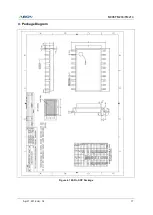
Page 17: ...MC96FM204 FM214 April 7 2016 Ver 1 8 17 4 Package Diagram Figure 4 1 20 Pin SOP Package ...
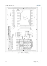
Page 18: ...MC96FM204 FM214 18 April 7 2016 Ver 1 8 Figure 4 2 20 Pin TSSOP Package ...
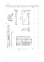
Page 19: ...MC96FM204 FM214 April 7 2016 Ver 1 8 19 Figure 4 3 16 Pin SOP Package ...
Page 20: ...MC96FM204 FM214 20 April 7 2016 Ver 1 8 Figure 4 4 16 Pin TSSOP Package ...


