MC96FM204/FM214
78
April 7, 2016 Ver. 1.8
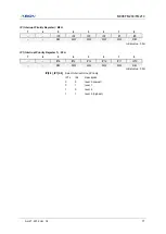
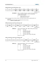
EIFLAG (External Interrupt Flag Register) : A0H
7
6
5
4
3
2
1
0
–
–
FLAG12
FLAG11
FLAG3
FLAG2
FLAG1
FLAG0
–
–
R/W
R/W
R/W
R/W
R/W
R/W
Initial value : 00H
EIFLAG0[5:0]
When an external interrupt is occurred, the flag becomes
‘1’.
The flag is cleared by writing
‘0’ to the bit or automatically
cleared by INT_ACK signal
0
External Interrupt not occurred
1
External Interrupt occurred
Note) Do not use the
“direct bit test and branch” instruction for input port, more detail information is at
Appendix B.
Example) Avoid direct input port bit test and branch condition as below
If(FLAG0)
→
if(EIFLAG & 0x01)
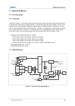
EIPOL0 (External Interrupt Polarity 0 Register): A4H
7
6
5
4
3
2
1
0
POL3
POL2
POL1
POL0
R/W
R/W
R/W
R/W
R/W
R/W
R/W
R/W
Initial value: 00H
EIPOL0[7:0]
External interrupt (EINT0, EINT1, EINT2, EINT3) polarity selection
POLn[1:0]
Description
0
0
No interrupt at any edge
0
1
Interrupt on rising edge
1
0
Interrupt on falling edge
1
1
Interrupt on both of rising and falling edge
Where n =0, 1, 2 and 3
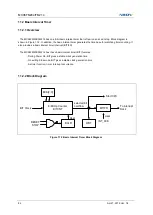
EIPOL1 (External Interrupt Polarity 1 Register): A5H
7
6
5
4
3
2
1
0
–
–
–
–
POL12
POL11
–
–
–
–
R/W
R/W
R/W
R/W
Initial value: 00H
EIPOL1[3:0]
External interrupt (EINT11, EINT12) polarity selection
POLn[1:0]
Description
0
0
No interrupt at any edge
0
1
Interrupt on rising edge
1
0
Interrupt on falling edge
1
1
Interrupt on both of rising and falling edge
Where n =11 and 12
Summary of Contents for MC96FM204
Page 17: ...MC96FM204 FM214 April 7 2016 Ver 1 8 17 4 Package Diagram Figure 4 1 20 Pin SOP Package ...
Page 18: ...MC96FM204 FM214 18 April 7 2016 Ver 1 8 Figure 4 2 20 Pin TSSOP Package ...
Page 19: ...MC96FM204 FM214 April 7 2016 Ver 1 8 19 Figure 4 3 16 Pin SOP Package ...
Page 20: ...MC96FM204 FM214 20 April 7 2016 Ver 1 8 Figure 4 4 16 Pin TSSOP Package ...


