MC96FM204/FM214
April 7, 2016 Ver. 1.8
115
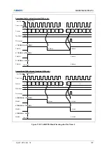
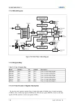
11.8.3 Data Transmit / Receive Operation
User can use SPI for serial data communication by following step
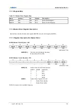
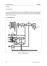
1. Select SPI operation mode(master/slave, polarity, phase) by control register SPICR.
2. When the SPI is configured as a Master, it selects a Slave by SS signal (active low).
When the SPI is configured as a Slave, it is selected by SS signal incoming from Master
3. When the user writes a byte to the data register SPIDR, SPI will start an operation.
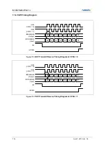
4. In this time, if the SPI is configured as a Master, serial clock will come out of SCK pin. And Master shifts the
eight bits into the Slave (transmit), Slave shifts the eight bits into the Master at the same time (receive). If the
SPI is configured as a Slave, serial clock will come into SCK pin. And Slave shifts the eight bits into the Master
(transmit), Master shifts the eight bits into the Slave at the same time (receive).
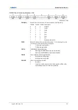
5. When transmit/receive is done, SPIIFR bit will be set. If the SPI interrupt is enabled, an interrupt is requested.
And SPIIFR bit is cleared by hardware when executing the corresponding interrupt. If SPI interrupt is disable,
SPIIFR bit is cleared when user read the status register SPISR, and then access (read/write) the data register
SPIDR.
11.8.4 SS pin function
1. When the SPI is configured as a Slave, the SS pin is always input. If LOW signal come into SS pin, the SPI
logic is active. And if
‘HIGH’ signal come into SS pin, the SPI logic is stop. In this time, SPI logic will be reset,
and invalidated any received data.
2. When the SPI is configured as a Master, the user can select the direction of the SS pin by port direction
register (P01IO). If the SS pin is configured as an output, user can use general P01IO output mode. If the SS
pin is configured as an input,
‘HIGH’ signal must come into SS pin to guarantee Master operation. If ‘LOW’
signal come into SS pin, the SPI logic interprets this as another master selecting the SPI as a slave and
starting to send data to it. To avoid bus contention, MS bit of SPICR will be cleared and the SPI becomes a
Slave and then, SPIIFR bit of SPISR will be set, and if the SPI interrupt is enabled, an interrupt is requested.
NOTES)
-
When the SS pin is configured as an output at Master mode, SS pin’s output value is defined by user’s software
(P01IO). Before SPICR setting, the direction of SS pin must be defined
- If you don
’t need to use SS pin, clear the SSENA bit of SPISR. So, you can use disabled pin by P0IO freely. In
this case, SS signal is driven by
‘HIGH’ or ‘LOW’ internally. In other words, master is ‘HIGH’, salve is ‘LOW’
- When SS pin is configured as input, if
‘HIGH’ signal come into SS pin, SS_HIGH flag bit will be set. And you can
clear it by
writing ‘0’.
Summary of Contents for MC96FM204
Page 17: ...MC96FM204 FM214 April 7 2016 Ver 1 8 17 4 Package Diagram Figure 4 1 20 Pin SOP Package ...
Page 18: ...MC96FM204 FM214 18 April 7 2016 Ver 1 8 Figure 4 2 20 Pin TSSOP Package ...
Page 19: ...MC96FM204 FM214 April 7 2016 Ver 1 8 19 Figure 4 3 16 Pin SOP Package ...
Page 20: ...MC96FM204 FM214 20 April 7 2016 Ver 1 8 Figure 4 4 16 Pin TSSOP Package ...


