ABB i-bus
®
KNX
Product Overview
3.4.4.2
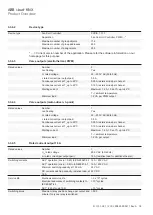
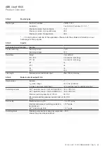
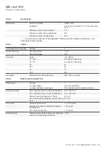
Device type
Device type
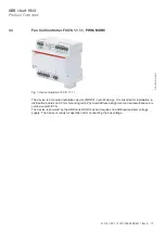
Fan Coil Controller
FCC/S 1.1.2.1
Application
Fan Coil Unit Controller, PWM, manual opera-
tion/…*
Maximum number of group objects
116
Maximum number of group addresses
255
Maximum number of assignments
255
* … = Current version number of the application. Please refer the software information on our
homepage for this purpose.
3.4.4.3
Valve outputs (electrothermal, PWM)
Rated values
Number
2
non-floating
Yes
U
n
rated voltage
24…230 V AC (50/60 Hz)
I
n
rated current (per output pair)
0.5 A
Continuous current at T
u
up to 20°C
0.25 A resistive load per channel
Continuous current at T
u
up to 45°C
0.15 A resistive load per channel
Starting current
Maximum 1.6 A, 10 s at T
u
up to 45°C
Minimum load
1.2 VA per PWM output
3.4.4.4
Valve outputs (motor-driven, 3-point)
Rated values
Number
1
non-floating
Yes
U
n
rated voltage
24…230 V AC (50/60 Hz)
I
n
rated current (per output pair)
0.5 A
Continuous current at T
u
up to 20°C
0.25 A resistive load per channel
Continuous current at T
u
up to 45°C
0.15 A resistive load per channel
Starting current
Maximum 1.6 A, 10 s at T
u
up to 45°C
Minimum load
1.2 VA per PWM output
3.4.4.5
Rated current output 16 A
Rated values
Number
1
U
n2
rated voltage
250 V AC (50/60 Hz)
I
n2
rated current (per output pair)
16 A (resistive load for additional heater)
Switching currents
AC3* operation (cos ϕ = 0.45) to EN 60947-4-1 16 A / 230 V AC
AC1* operation (cos ϕ = 0.8) to EN 60947-4-1
16 A / 230 V AC
Minimum switching capacity at 100 mA
24 V AC
DC current switching capacity, resistive load, at
16 A
24 V DC
Service life
Mechanical service life
> 3 x 10⁶ cycles
Electrical endurance of switching contacts to
IEC 60947-4-1
> 10⁶ cycles
AC1* (240 V/cos ϕ=0.8)
> 10⁵ cycles
Switching times
Maximum relay position change per output and
minute if only one relay is switched.
> 500
FCC/S 1.X.X.1 | 2CDC 508 200 D0211 Rev A 26

