ABB i-bus
®
KNX
Parameters
FCC/S 1.X.X.1 | 2CDC 508 200 D0211 Rev A 258
7.8.1.2.1.1.1
—
Dependent Parameter
Voltage range valve control value
This parameter is only displayed if the
Valve type
parameter is parameterized with the
Normal
op-
tion.
Options:
0 – 10 V
1 – 10 V
2 – 10 V
10 – 0 V
This parameter defines the function of the valve output. Depending on the selection, the control
value is converted to the corresponding voltage range.
Note
Valve drives closed if de-energized (0…10 V; 1…10 V; 2…10 V):
If no current flows in the valve drive, the valve is closed. If current flows in the valve drive, the
valve opens.
Valve drives opened if de-energized (10…0 V):
If no current flows in the valve drive, the valve opens. If current flows in the valve drive, the valve
then closes.
Note
The technical data for the valve drive must be observed.
On the selection of the
1 – 10 V
and
2 – 10 V
options, the output voltage is limited to this range. To
make sure that the valve is always closed completely, on the actuation of the valve with 0 % (=
closed), the control value 0 V is output nevertheless. If the control value is greater than 0 %, the
lower limit (1 V or 2 V) is used directly for the actuation.
If the DPT 5.001 (percent) is used for actuation, the value of the group object may be displayed as
0 %, but the actual value of the group object may be slightly above that and a 0 is only displayed
due to the rounding to integer values. This situation can be detected by viewing the hexadecimal
value (this is then e.g. 0x0001) or changing to a different DPT (e.g. 5.005).
7.8.1.2.1.1.2
6-way valve
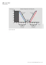
On use as a 6-way valve, the valve output is used for heating and for cooling. The special layout of
the 6-way valve makes it possible to use both pipes independent of each other. To safeguard this
functionality, the drive control value is divided into a range for cooling and a range for heating. Be-
tween these ranges there is a dead zone in which the valve is closed.
If the control value is in the actuation range for cooling, the flow for cooling is opened correspond-
ing to the control value and the flow for heating shut off. The same applies vice versa.
The following illustration shows the relationship between voltage range and control value. The fol-
lowing example values have been selected:
•
Voltage for maximum cooling: 2 V
•
Voltage for minimum cooling: 5 V
•
Voltage for maximum heating: 7 V
•
Voltage for minimum heating: 10 V

