


ABB i-bus
®
KNX
Product Overview
FCC/S 1.X.X.1 | 2CDC 508 200 D0211 Rev A 71
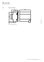
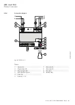
3.11.2
Connection diagram
A
B
a
d
c
b
10
12
14
9
11
13
a
b
c
16
15
d
U
n1
D
N.C.
C
7
8
5
6
0 V 0-10 V
4
1
3
2
U
n
A
B
U
= 230 V
~
n1
I
= 16 A
n1
I = 0,5 A
n
U = 24 - 230 V
~
n
N
L1
N
L3
L2
10
11
15
12
13
14
16
Fig. 27: FCC/S 1.5.2.1
2CDC072019F0017
—
Legend
1
Label carrier
2
Programming LED
3
Programming button
4
Bus connection terminal
5
Cover cap
6
Inputs (a, b, c, d)
7
Valve output A
8
Valve output B
9
Fan output
10
Auxiliary relay
11
Valve output changeover button/LED
12
Valve output open/close button/LED
13
Relay output open/close button/LED
14
Switch fan speed button/LED
15
Manual operation button/LED
16
Inputs (a, b, c, d) status indicator LEDs


