


ABB i-bus
®
KNX
Product Overview
FCC/S 1.X.X.1 | 2CDC 508 200 D0211 Rev A 37
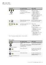
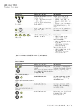
Button/LED
Description/Function
LED indicator
Fan speed
Switches the fan speed in the fol-
lowing sequence:
•
0 > 1 > 2 > 3 > 0 > 1…
(Long push of the button always
switches to 0.)
Indication of the current fan speed
with speed switching:
•
Speed 0: all LEDs off
•
Speed 1: LED 1 on
•
Speed 2: LEDs 1 &2 on
•
Speed 3: all LEDs on
Indication of the current fan speed
with changeover switching:
•
Speed 0: all LEDs off
•
Speed 1: LED 1 on
•
Speed 2: LED 2 on
•
Speed 3: LED 3 on
Manual operation
Activate KNX mode with a short
press of the button.
On: On: The device is in Manual
Off: Device is in KNX mode
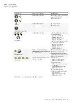
Inputs a...x
LED indication depending on how
the inputs are used.
Binary sensor:
•
LED on: Contact closed
•
LED off: Contact open
Temperature sensor:
•
LED on: Temperature sensor
connected
•
LED flashing: Error (cable
break/short circuit)
Analog room control unit
•
LED on: Analog room control
unit connected
•
LED flashing: Error (cable
break/short circuit)
Table 11: Operating and display elements – manual operation
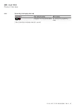
KNX operation
Button/LED
Description/Function
LED indicator
Valve output changeover
Switches between valve A and
valve B
If a valve output has been disabled
in the parameters, it is not possible
to select the valve.
On: Indicates the selected valve
Flashing: Error (overload/short cir-
cuit) on the output concerned
Open valve output/increase control
value
Button without function
On: Valve control value at 100%
Flashing: Indicates a fault, e.g.
overload/short circuit
Close valve output/decrease con-
trol value
Button without function
On: Valve control value at 0 %
Flashing: Indicates a fault, e.g.
overload/short circuit


