


ABB i-bus
®
KNX
Function
FCC/S 1.X.X.1 | 2CDC 508 200 D0211 Rev A 81
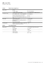
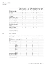
FCC/S 1.1.X.1 and FCC/S 1.2.X.1 and FCC/S 1.4.1.1
Function
Fan output
Number of fan speeds (5 A)
1-speed
X
2-speed
X
3-speed
X
Switching function
X
Step switching
X
Table 27: Functions of the fan output
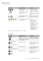
FCC/S 1.3.X.1 and FCC/S 1.5.X.1
Function
Fan output
Continuous fan 0-10 V, freely selectable voltage range
X
Error detection
Overload/short circuit
X
Table 28: Functions of the fan output
4.4.3
Relay output
This chapter does not apply to the FCC/S 1.4.X.1.
Function
Relay output
Use by internal controller for electric heater
X
Use as independent switching output
X
Internal connection to the device input
X
Table 29: Function of the relay output
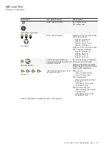
4.5
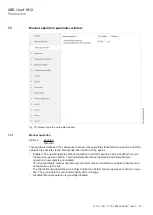
Integration into the i-bus® Tool
The device possesses and interface to the i-bus® Tool.
The i-bus® Tool can be used to read out data and test functions on the connected device.
In addition, values can be simulated for test purposes. If there is no communication, output values
are no longer sent to the bus, even if they are simulated using the i-bus® Tool.
The i-bus® Tool can be used to specify controller parameters to test the correct adjustment of the
room thermostat. It is also possible to switch between the various room states (Comfort, Standby,
Economy, Building Protection) to test the device reaction. The device's physical inputs and outputs
can be tested via the i-bus® Tool.
The i-bus® Tool can be downloaded for free from our website (www.abb.com/knx).
A description of the functions is provided in the i-bus® Tool online help.


