Page 40 May 2014 – TD 293 OPERATING MANUAL – SmartGuard 5100/5120/5300/5320
General description:
The Serial Sensor’s product identification together with its parameters definitions (name, unit, data type,
max and min limits) are stored in the layout.
SmartGuard supports both RS232 and RS422 sensors; COM1 can be set for either of the two. Be sure to use
what is required for the actual sensor.
In order to save power SmartGuard controls the power for each individual sensor. The serial sensors can be
powered through pin 9 in the DSUB connector or through the separate M12 connector adjacent to the DSUB
connector if higher currents are drawn by the sensor. Sensors may need a certain warm up time from power
up before measured parameters are within specified accuracy. This must be specified in the configuration,
refer chapter 6.2.3, in order for SmartGuard to take this into account when the recording sequence is
arranged internally. Also sensor requirement for a minimum time with power off can be set. A Command
Polled sensor may be set to be continuously powered if this is required for a proper operation.
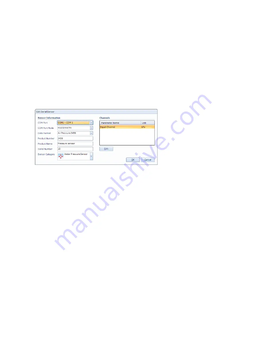
Press Add below the list of serial
sensors, refer Figure 6-2, and
enter serial sensor information
as shown in Figure 6-5.
To edit an existing sensor layout:
•
Select the sensor from the list
•
Press
Edit
below the list of
serial sensors to edit existing
layout.
Note! Some changes in the layout will change the sensors identity and hence the sensor must be
reconfigured. Open the device configuration the reconfigure the sensor, refer CHAPTER 4.
Procedure for Serial Sensors layout:
•
Select
COM Port
where this sensor is physically connected to SmartGuard
•
Select
COM Port Mode
:
RS232 or RS422 as appropriate
•
Select a defined data format from the drop down list, refer chapter 6.2.1
•
Type the product number and name, and the actual sensor’s serial number
•
Select an appropriate icon from the drop-down list
•
Select each parameter’s data channel in the
Channels
list and press
Edit
to set parameter name (e.g.
Wind Speed), measurement unit (e.g. m/s) and max (e.g. 40) and min value (e.g. 0) limits, refer Figure 6-6.
By filling in a format specification you can decide number of digits etc. when this value is presented in e.g.
the collectors numerical viewer.
Figure 6-5 Edit serial sensor information.


