LSM 710 and LSM 780
LEFT TOOL AREA AND HARDWARE CONTROL TOOLS
Systems
Acquisition Tab
Carl Zeiss
02/2010 M60-1-0025
e
89
Range Select
produces a XZ scan as described above. Dragging the green line moves the whole stack
updating the
Focus Position
accordingly. Dragging a red line changes the
Number of Slices
and
therefore the
Range
of the stack keeping the
Focus Position
unchanged. The second red line is set to
keep the green line in the center of the stack.
The scanning
Direction
for acquiring the stack using the Piezo can be performed unidirectional or
bidirectional. This means the data acquisition is done also when the focus is moving backwards to the
initial start position of the stack. This only applies if multiple stacks are acquired in a time series. For one
stack only the direction settings have no effect. A correction slider
Corr Z
is available to correct for
possible shifts of the stacks in Z.
5.2.12.4
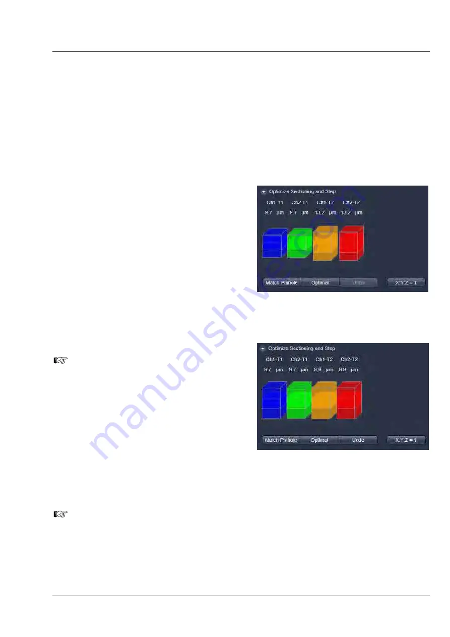
Optimize Sectioning and Stack
The
Optimize Sectioning and Step
function
helps to set the
Optimal
for a given excitation
wavelength, detection range and used objective. If
more than one channel is used, the optimal
interval is determined for each channel
independently. For given pinhole diameters, half
the value of the currently smallest optical section
(typically of the channel which detects the shortest
wavelength range) is used to determine the
optimum interval. For example if the optical section
for the channel detecting DAPI is calculated as
1.5 µm, the optimal interval is 0.75 µm (Nyquist
criteria). It is recommended to start with setting
one airy unit (1
AU) for all channels in the
Channels
tool before starting to optimize.
Note that the actual values might slightly
vary around these theoretical values.
This now produces stronger overlapping optical
sections for the channels detecting longer
wavelength ranges. The optical sections are not
identical and the image data acquired are
redundant. Especially for analyzing co-localization
of signals from different channels the optical
sections have to match.
The function
Match Pinhole
sets all pinholes to
match this optimal interval. The pinhole diameter is
set such that the values of the resulting optical
sections from the different channels are identical
and have double the value of the optimal interval.
Note that the settings of the pinhole might not result in matching optical sections. This is then
due to the chosen objective which would require a smaller setting of the pinhole that is
mechanically not possible. In this case chose a higher magnifying objective or start with a larger
pinhole setting for the channel detecting the shortest wavelength range.
Undo
resets the just before altered value.
X:Y:Z = 1
matches the settings in Z to the settings in X and Y. This produces a cubical voxel.
Fig. 79
Optimize Sectioning and Step:
Optimal Interval is set starting with one
Airy unit for all channels
Fig. 80
Optimize Sectioning and Step:
Match Pinhole to Step resulting in equal
optical sections for all channels


