background image

Spectral Imaging

The acquisition of spectral data becomes necessary

where the overlapping emission signals of multiple-

labeled specimens have to be separated, or where

the cellular parameter to be measured is coded by

changes of the emission spectrum (e.g., FRET and

ratio imaging of ion concentrations).

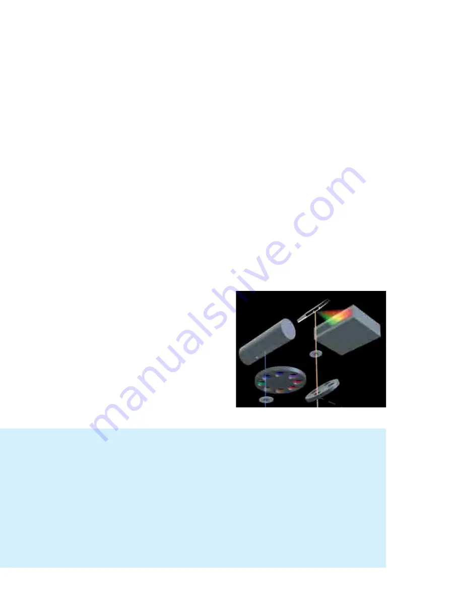
The LSM 510 META is a system for the fast acqui-
sition of images of high spectral resolution. The
hardware enabling this functionality consists of a
spectrally dispersive element, a photomultiplier
(PMT) with 32 parallel detection channels (META
Detector), and special electronic circuitry for
detector control and signal amplification. 

Whereas the beam paths for conventional and
META detection are identical on the excitation
side, the emission beam for spectral detection,
after having passed the pinhole, hits a reflective
grating. The grating spreads the beam into a spec-
trum and projects it onto the surface of the linear
detector array. Each of the 32 PMT elements in
that array thus registers a different part of the
spectrum, each part having a width of 10 nm. The
result is a lambda stack of XY images in which
each image represents a different spectral window.

META Detector
Part of the beam path in the 
LSM 510 META scanning head

1  Confocal pinhole
2  Reflective grating for spectral 

dispersion

3 META Detector with 

32 separate PMT elements

14

The procedure for a lambda stack

1

Select the spectral range in the 

Lambda-Mode

2

Activate the excitation laser lines

3

Carefully control the dynamic range to avoid over- and underexposed pixels 

(Range Indicator)

4

In multiple-labeled specimens, vary the power of the respective laser lines instead of the 

Amplifier Gain,

in order to match the signal intensities of the fluorochromes

5

Record the lambda stack

6

Display the data in one of the modes:

Gallery, Single, Slice, Max 

or

λ

-coded

1

2

3

Содержание LSM 710

Страница 1: ...i pj TNMI ipj TUMI ipj TNM kilI ipj TUM kil P l j c OMNM wbk OMNM...

Страница 2: ...specifications are subject to change the manual is not covered by an update service Unless expressly authorized forwarding and duplication of this document and the utilization and communication of its...

Страница 3: ...lly solve your work problem It represents a practical tip which will help you to find out which settings and methods are capable of improving or accelerating a procedure The HOT SURFACE symbol warns a...

Страница 4: ...uces you to the performance features of your LSM 710 and LSM 780 systems 4 System Operation In this section you will find the most important steps and procedures of the LSM menu structure The step by...

Страница 5: ...1 8 Notes on Handling the Laser Components and Illumination Systems 22 1 9 Notes on Handling the Computer and Data Media 25 1 10 Notes on Care Maintenance and Service 26 1 11 User Interface 28 1 11 1...

Страница 6: ...aim under warranty including parts not directly affected by such action This also includes the modification of the system computer with new cards etc by the user The use of a camera at the base port o...

Страница 7: ...laser products DIN EN 61326 Electrical equipment for control technology and laboratory use EMC requirements Low voltage directive 2006 95 EG EMC directive 2004 108 EG The company works according to a...

Страница 8: ...1 1 9 kVA max Phase 2 1 5 kVA max Phase 3 2 6 kVA max 2 phases at 25 A Phase 1 3 2 kVA max Phase 2 2 8 kVA max Power consumption 4000 VA max 4000 VA max Class of protection I I Type of protection IP...

Страница 9: ...ems Power Requirements Carl Zeiss 02 2010 M60 1 0025 e 5 Fig 2 Power connector for LSM 710 and LSM 780 systems and components Free reserve outlets may be used to supply power to additional equipment N...

Страница 10: ...wer Requirements Systems 6 M60 1 0025 e 02 2010 Fig 3 Power connector for LSM 710 and LSM 780 systems with Laser In Tune and components Free reserve outlets may be used to supply power to additional e...

Страница 11: ...the same position Two door interlocks can be connected The LSM 710 and LSM 780 systems are controlled by a remote control This remote control contains the main switch for the system and the key switc...

Страница 12: ...120 90 77 120 Active anti vibration table NLO for Mai Tai Laser or Chameleon 180 150 75 200 Active anti vibration table NLO for two microscope configuration 250 150 75 400 Scanning Module LSM 710 LSM...

Страница 13: ...commissioning of the LSM 710 and LSM 780 systems and the ConfoCor 3 systems must be performed by authorized Carl Zeiss service staff The system should not be used prior to instruction by a Carl Zeiss...

Страница 14: ...on or even damage them The openings for ventilation must not be covered There are hot surfaces on the HBO and HAL lamp The HBO 50 and 100 W XBO 75 W and X cite 120 lamps used on the light microscopes...

Страница 15: ...You will receive a free replacement Description of labels Caution Faults and hazards that might arise during operation which might cause damage to the unit or injury to the user Attention Laser radia...

Страница 16: ...SAFETY LSM 710 and LSM 780 Carl Zeiss Warning and Information Labels Systems 12 M60 1 0025 e 02 2010 Fig 6 Warning and information labels on the Axio Observer Z1 microscope with the LSM 710 LSM 780 s...

Страница 17: ...ES ON DEVICE SAFETY Systems Warning and Information Labels Carl Zeiss 02 2010 M60 1 0025 e 13 Fig 7 Warning and information labels on the Axio Observer Z1 microscope with the LSM 710 LSM 780 scanning...

Страница 18: ...LSM 780 Carl Zeiss Warning and Information Labels Systems 14 M60 1 0025 e 02 2010 Fig 8 Warning and information labels on the Axio Observer Z1 microscope with the LSM 710 and LSM 780 scanning module a...

Страница 19: ...Y Systems Warning and Information Labels Carl Zeiss 02 2010 M60 1 0025 e 15 Fig 9 Warning and information labels on the Axio Observer Z1 microscope with the LSM 710 LSM 780 scanning module and the Con...

Страница 20: ...E SAFETY LSM 710 and LSM 780 Carl Zeiss Warning and Information Labels Systems 16 M60 1 0025 e 02 2010 Fig 10 Warning and information labels on the Axio Imager Z2 microscope with the LSM 710 LSM 780 s...

Страница 21: ...TES ON DEVICE SAFETY Systems Warning and Information Labels Carl Zeiss 02 2010 M60 1 0025 e 17 Fig 11 Warning and information labels on the Axio Imager Z2 microscope with the LSM 710 LSM 780 scanning...

Страница 22: ...E SAFETY LSM 710 and LSM 780 Carl Zeiss Warning and Information Labels Systems 18 M60 1 0025 e 02 2010 Fig 12 Warning and information labels on the Axio Examiner microscope with the LSM 710 LSM 780 sc...

Страница 23: ...TES ON DEVICE SAFETY Systems Warning and Information Labels Carl Zeiss 02 2010 M60 1 0025 e 19 Fig 13 Warning and information labels on the Axio Examiner microscope with the LSM 710 LSM 780 scanning m...

Страница 24: ...M 780 Carl Zeiss Warning and Information Labels Systems 20 M60 1 0025 e 02 2010 Fig 14 Warning and information labels on the laser and electronic rack Fig 15 Warning and information labels on the lase...

Страница 25: ...EVICE SAFETY Systems Warning and Information Labels Carl Zeiss 02 2010 M60 1 0025 e 21 Fig 16 Warning and information labels on the Laser Rack In Tune Fig 17 Warning and information labels on the Lase...

Страница 26: ...specified herein may result in hazardous radiation exposure The following laser types are currently intended for use in the LSM 710 and LSM 780 systems The use of any other lasers as the ones listed...

Страница 27: ...e commissioning the laser The LSM system and the Ar laser are equipped with a key interlock Always store keys for laser key switches and if applicable keys for further laser power supply units where t...

Страница 28: ...commend not to look through the eyepiece when rotating the reflector turret Especially we do not recommend the use of the reflector turret controls located on the microscope stand since this leads to...

Страница 29: ...data Also never open the metal cover on diskette cases A diskette s surface can also be destroyed by touching it When handling CDs CD ROMs or DVDs do not touch the data side of the disc the side of t...

Страница 30: ...n the hardware itself and also in Fig 2 and Fig 3 For exchanging fuses proceed as follows Open the fuse carrier by turning 90 clockwise Pull out the fuse carrier and replace the fuse by a new one of t...

Страница 31: ...s To do this use a clean cloth that has been moistened in a mixture of water and some detergent do not use any solvent however Dry with a lint free cloth Cleaning glass surfaces Glass surfaces that ha...

Страница 32: ...connectors LSM 780 710 filter wheel 1 11 1 Mounting and Dismounting Lamps TPMT and Switching Mirror The ports of the lamps the switching mirror and the transmission PMT are equipped with hardware inte...

Страница 33: ...screw of the port to fix the cap Make sure the pins of the cap depress the sensors of the sensor ring Do not remove the sensor ring from the microscope This might result in failure of laser safety an...

Страница 34: ...owly pull the LSM BiG Fig 22 4 away from the port For mounting the LSM BiG onto the port make sure the pins and the electronic connections of the safety interface match closely Push the LSM BiG to the...

Страница 35: ...nd with an angled adapter on the HBO lamp house the adapter will remain on the stand while the lamp house is removed Moving the scan heads between Axio Observer Z1 Axio Examiner and Axio Imager Z2 Loo...

Страница 36: ...black tube Fig 27 2 which is fixed to the scan head Fig 27 3 Now the tube can be removed and you can proceed as described above For rearranging the beam housing first screw the tube onto the small bl...

Страница 37: ...miner Fig 28 1 or on the rear side of the microscope Axio Imager Z2 or Axio Observer Z1 Fig 29 1 and Fig 30 1 This connection has to be unplugged from the microscope which is not in use and plugged in...

Страница 38: ...se It can be chosen via the icon Stand Select 1 11 4 Changing the Filter Wheel in the LSM 710 and LSM 780 systems You can remove and replace filter wheels by push and click When opening the cover the...

Страница 39: ...the ConfoCor 3 detection head from its attachment to the LSM 710 LSM 780 Laser light can escape the system through the external port used as the attachment site for the ConfoCor 3 that can lead to bod...

Страница 40: ...odule Disengage the filter module Fig 35 4 from the upper spring elements Fig 35 2 of the filter insert Fig 35 5 by tilting it forward then lift it off the lower spring elements Fig 35 1 and remove th...

Страница 41: ...B 16 pin LEMO ECJ 2B Power consumption less than 20 W CAN 15 pin HD Sub D female 15 pin HD Sub D female Optional CAN Port Service Port RS232 9 pin Sub D male Service Port APD 1 2 Triax BNT Photon puls...

Страница 42: ......

Страница 43: ...SM 780 equipped with Two Photon Laser NLO for dual stand 3 2 2 Power Requirements 4 2 3 Physical Dimensions 5 2 4 Dimension of Shipment Crates 6 2 5 Environmental Requirements 6 2 6 Vibrations 7 2 7 M...

Страница 44: ...neath the table If present the laser Rack In Tune is located on top of the Laser Rack of the LSM 710 and LSM 780 The total height of this rack is then 1 m 2 1 2 LSM 710 and LSM 780 with ConfoCor 3 on...

Страница 45: ...the table If present the Laser Rack In Tune is located on top of the Laser Rack of the LSM 710 and LSM 780 The total height of these racks is then 1 m 2 1 4 LSM 710 and LSM 780 equipped with Two Phot...

Страница 46: ...racteristic C according to IEC EN 60898 Line voltage 3 N PE 400 230 V AC 10 2 N Ground 240 120 V AC 10 Line frequency 50 60 Hz 50 60 Hz LSM incl VIS laser Max current Power 3 phases at 16 A Phase 1 1...

Страница 47: ...ive anti vibration table NLO for Mai Tai Laser or Chameleon 180 150 75 200 Active anti vibration table NLO for two microscope configuration 250 150 75 400 Scanning Module LSM 710 LSM 780 50 45 22 28 M...

Страница 48: ...box 139 94 114 150 Accessories small box 112 94 96 100 Microscope stand max size 96 89 94 50 Laser Rack In Tune without laser 104 94 72 10 Laser In Tune 74 60 40 30 2 5 Environmental Requirements 1 O...

Страница 49: ...es from Carl Zeiss and their accessories can be accommodated Z motor DC servomotor opto electronically coded Least Z interval 25 nm Axio Observer Z1 SP or RP 30 nm Axio Examiner 10 nm Axio Imager Z2 2...

Страница 50: ...32 GaAsP 2 PMT fluorescence channels simultaneously LSM 780 1 transmitted light channel PMT and up to 5 NDD channels or 2 10 NDD channels Non descanned detectors PMT 2 monitor diodes for maintenance p...

Страница 51: ...Diode laser pulsed cw 405 nm 30 mW cw mode max power ca 15 mW on fiber out range 0 6 15 mW w o attenuator attenuation by a factor of 25 pulsed mode repetition rate 20 50 80 MHz mean power 20 MHz ca 0...

Страница 52: ...SETUP REQUIREMENTS LSM 710 and LSM 780 Carl Zeiss System Overview LSM 710 and LSM 780 Systems 10 M60 1 0025 e 02 2010 2 14 System Overview LSM 710 and LSM 780...

Страница 53: ...LSM 710 and LSM 780 SETUP REQUIREMENTS Systems System Overview LSM 710 and LSM 780 Carl Zeiss 02 2010 M60 1 0025 e 11...

Страница 54: ...SETUP REQUIREMENTS LSM 710 and LSM 780 Carl Zeiss System Overview LSM 710 and LSM 780 with ConfoCor 3 Systems 12 M60 1 0025 e 02 2010 2 15 System Overview LSM 710 and LSM 780 with ConfoCor 3...

Страница 55: ...LSM 710 and LSM 780 SETUP REQUIREMENTS Systems System Overview LSM 710 and LSM 780 with ConfoCor 3 Carl Zeiss 02 2010 M60 1 0025 e 13...

Страница 56: ......

Страница 57: ......

Страница 58: ......

Страница 59: ...es This Quick Guide does NOT replace the detailed information available in the full user manual or in the manual of the respective microscopes Axio Imager Axio Observer Axio Examiner Also this Quick G...

Страница 60: ...of the X Cite 120 HBO 100 lamp for reflected light illumination via the power supply as described in the respective operating manual Switching on the Ar ML Laser If the Ar ML laser is required switch...

Страница 61: ...tes the entire software package for new image acquisition and analysis The Image Processing mode ignores all hardware and activates only data handling and image processing functionality for already ac...

Страница 62: ...4 02 2010 Fig 4 ZEN Main Application Window after Startup with empty image container Fig 5 ZEN Main Application Window after Startup with several images loaded...

Страница 63: ...the image According to the chosen view tab the required view controls appear in View Control Tabs below each image File management and data handling tools are found in the Right Tool Area see Fig 4 a...

Страница 64: ...your personal preferences Fig 7 Setting up conventional confocal software for a specific experiment can take a long time and is often tedious to repeat With ZEN these adjustments have to be done only...

Страница 65: ...written by a new scan Multi dimensional scans or saved images will never be over written and a new scan will then automatically create a new image document Acquired data is not automatically saved to...

Страница 66: ...File Menu The ZEN File Browser can be used like the WINDOWS program file browser Images can be opened by double click and image acquisition parameters are displayed with the thumbnails Fig 9 For more...

Страница 67: ...the lasers are turned on automatically The Laser Life Extender function of the software shuts all lasers off if ZEN is not used for more than 15 minutes To manually switch lasers on or off Click the...

Страница 68: ...press the Online button for your actions to take effect immediately Then open the Ocular tool to configure the components of your microscope like filters shutters or objectives Fig 11 Selecting an obj...

Страница 69: ...ter set by clicking on it Storing the microscope settings Microscope settings can be stored as configurations Fig 13 by typing a config name in the pull down selector and pressing the save button Fast...

Страница 70: ...rrow in the dye list and simply choose the dye s you want to use in your experiment from the list dialogue In this dialogue the dyes can be also searched by typing the name in the search field Fig 14...

Страница 71: ...splayed way for the dyes chosen If the option Linear Unmixing is selected the system is set in the lambda mode automatically Pressing the Auto Exposure button will then optimize the settings of the Ga...

Страница 72: ...uble and triple labeling line by line or frame by frame Advantage Only one detector and one laser are switched on at any one time This reduces cross talk Disadvantage slower image acquisition Open the...

Страница 73: ...box of the selected channel Ch 1 4 monitor diode ChM QUASAR detectors ChS1 8 transmission ChD for the scanning procedure and assigning a color to the channel Select the appropriate filters and activat...

Страница 74: ...and channels Frame Tracks are switched during scanning frame by frame The following settings can be changed between tracks Laser line and intensity all filters and beam splitters the channels incl se...

Страница 75: ...can Speed slider in the Acquisition Mode tool Fig 20 to adjust the scan speed A higher speed with averaging results in the best signal to noise ratio Scan speed 8 usually produces good results Use spe...

Страница 76: ...mode in the Acquisition Mode tool Select the number of lines or frames to average Adjusting pinhole size Select the Channels tool in the Left Tool Area Set the Pinhole size to 1 AU Airy unit for best...

Страница 77: ...automatic pre adjustment of detector gain and offset Select Live for continuous fast scanning useful for finding and changing the focus Select Continuous for continuous scanning with the selected sca...

Страница 78: ...inhole to 1 Airy Unit Fig 25 Set the Gain Master high When the image is saturated reduce AOTF transmission in the Laser control section of the Channels Tool Fig 25 using the slider to reduce the inten...

Страница 79: ...Stack Then focus on the lower specimen area where the recording of the Z Stack is to end Click on the Set Last button to set this lower position Click on the button to set number of slices to match th...

Страница 80: ...able extra information and hardware settings of your experiment Click on the Save button If you close an image which has not been saved a pop up window will ask you if you want to save it Choosing yes...

Страница 81: ...ration Open the System Configu ration tool to define the light path laser lines and pinhole position The Light Path and Pinhole panels of the System Configuration window display the selected track con...

Страница 82: ...t box Press the Count rate button to open the Real Time display window for the detector Count rate in all active channels Adjust the Laser power In the Laser Control panel to obtain a satisfactory cou...

Страница 83: ...window if highlighted Press the Count rate button to open the Real Time display window for the detector Count rate in all active channels This allows you to optimize your experiment by changing the l...

Страница 84: ...nt rate trace Press the Correlation button to display the correlation function Press the Photon counting histogram button to display the photon distribution per time unit Press the Data Options to han...

Страница 85: ...experiment Pressing the Reload button will open the current measurement if stored raw data are available This allows you to alter the parameters of your mathematical calculations Analyzing the data T...

Страница 86: ...ters in the Model table Pressing the Fit button will fit the current loaded correlation functions to the defined model The fitted data will be displayed in the Model and Result tables Pressing the Fit...

Страница 87: ...n use Shut down the computer Switch off the Ar ML laser with first the idle run switch Fig 2 3 and second the key switch Fig 2 1 then wait until the fan of the Argon laser has switched off Don t switc...

Страница 88: ......

Страница 89: ...M i c r o s c o p y f r o m C a r l Z e i s s Confocal Laser Scanning Microscopy Optical Image Formation Electronic Signal Processing Principles 337_Zeiss_Grundlagen_e 25 09 2003 16 16 Uhr Seite 2...

Страница 90: ...te of the art computer technology 1992 The LSM 410 is the first inverted micro scope of the LSM family 1997 The LSM 510 the first system of the LSM 5 family and a major breakthrough in confocal imagin...

Страница 91: ...e the transmission mode with conventional con trasting methods such as differential interference contrast DIC as well as to overlay the transmission and confocal fluorescence images of the same speci...

Страница 92: ...ignal Processing Sampling and Digitization 16 Types of A D conversion 17 Nyquist theorem 18 Pixel size 19 Noise 20 Resolution and shot noise resolution probability 21 Possibilities to improve SNR 23 S...

Страница 93: ...s of a photomultiplier tube PMT 3 Digitization of the object information contained in the electrical signal provided by the PMT for presentation the image data are displayed pixel by pixel from a digi...

Страница 94: ...only a point of the object at a time the point illuminated and the point observed i e image and object points are situated in conjugate planes i e they are focused onto each other The result is what...

Страница 95: ...he channels involved figure 3 left A confocal LSM can therefore be used to advan tage especially where thick specimens such as biological cells in tissue have to be examined by fluorescence The possib...

Страница 96: ...quantifying the changes The following section Part 1 page 6 ff deals with the purely optical conditions in a confocal LSM and the influence of the pinhole on image forma tion From this ideal values fo...

Страница 97: ...l diffraction limited case no optical aberrations homogeneous illumination of the pupil see Details Pupil Illumination the 3D PSF is of comet like rotationally symmetrical shape For illustration Figur...

Страница 98: ...ices of immersion liquid and mounting medium are not matched and or if the laser focus is at a great depth below the specimen surface see Hell S et al 9 PSFdet is also influenced by all these factors...

Страница 99: ...maller the pinhole diameter the more PSFdet approaches the order of magnitude of PSFill In the limit case PH 0 25 AU both PSFs are approxi mately equal in size and wave optical image formation laws cl...

Страница 100: ...diameters leads to a gain in resolution by the factor em exc via the Stokes shift 9 Resolution Resolution in case of large pinhole diameters PH 1AU is meant to express the separate visi bility both l...

Страница 101: ...ormal ized intensity of 1 The real relationships result by rotation of the section about the vertical Z axis Symmetry exists relative to the focal plane as well as to the optical axis Local intensity...

Страница 102: ...dominant for a given objective it is influenced exclusively by the pinhole diameter Likewise in the case of geometric optical confo cality there is a linear relationship between depth discrimination a...

Страница 103: ...diameters it is practical to regard the limit of PH 0 at first even though it is of no practical use In this case PSFdet and PSFill are identical The total PSF can be written as In fluorescence appli...

Страница 104: ...ions derived for PH 0 to the pinhole diameter range up to 1 AU to a good approximation The factors applicable to particular pinhole diameters can be taken from figure 10 It must also be noted that wit...

Страница 105: ...920 1000 800 1040 960 1120 880 1200 1280 1360 1440 1520 1600 0 0 5 1 0 1 5 2 0 2 5 3 0 3 5 4 0 4 5 5 0 1 1 1 1 2 1 3 1 4 504 488 520 536 552 568 600 Optical slice NA 1 3 n 1 52 496 nm Depth resolution...

Страница 106: ...erature the wave optical depth of field in a conventional microscope is sometimes termed depth resolution However a clear distinction should be made between the terms resolution and depth resolution 2...

Страница 107: ...ely small This is due to the efficiency of the system as a whole and the influencing factors involved such as quantum yield bleaching and saturation of fluorochromes the transmittance of optical ele m...

Страница 108: ...r cycle pixel time see figure 12 Integration The signal detection time has the same order of magnitude as the pixel time Integration is equivalent to an averaging of inten sities over a certain percen...

Страница 109: ...an that given by the Nyquist theorem undersampling part of the information will be lost This is evident in Figure 14c especially by the unresolved fine features A greater number of sampling points per...

Страница 110: ...oom factor influences not only the total magnification but also the resolution properties of the system With the more recent LSM systems of Carl Zeiss the number of sampling points can also be influ e...

Страница 111: ...ss in energy Moreover it should be considered that it depends on the signal level wich noise source dominates With high amplitude signals number of detected photons 10 000 laser noise is the dominatin...

Страница 112: ...with the influences of shot noise of the detected light and the scanning and digiti zation of the object The essential criterion is the discernability of object details Figure 17 page 22 shows the dep...

Страница 113: ...higher intensity of detected light less noise bet ter SNR For most fluorescent applications a pin hole diameter of about 1 AU has turned out to be the best compromise Fig 17 The graph shows the comput...

Страница 114: ...ions improves SNR by a factor of 2 3 dB The advantage of the Figures 18 and 19 Improvement of the signal to noise ratio In figure 18 top pixel time is varied while the number of signal acquisitions sc...

Страница 115: ...ing the excitation and emission beam paths is not a neu tral 80 20 beamsplitter1 but a dichroic beamsplit ter optimized for the particular fluorescence Fig 20 Three confocal images of the same fluores...

Страница 116: ...difficult problem of quantifying the interaction between resolution and noise in a confocal LSM is solved by way of the concept of resolution proba bility i e the unrestricted validity of the finding...

Страница 117: ...ribution e g optical slice n Refractive index of an immersion liquid NA Numerical aperture of a microscope objective PH Pinhole diaphragm of variable size arranged in the beam path to achieve optical...

Страница 118: ...scopy the following pages treat several aspects of particular importance for practical work with a Laser Scanning Microscope Details Pupil Illumination Optical Coordinates Fluorescence Sources of Nois...

Страница 119: ...f the point image in case of diffraction limited imaging the graph only shows the intensity curve in the X direction Figure 21 right shows the percentage efficiency as a function of pupil diameter in...

Страница 120: ...generally valid representation of the optical slice thickness in a confocal LSM In order to enable a representation of lateral and axial quantities independent of the objective used let us intro duce...

Страница 121: ...lows Fluorescence Details F Qe I photons sec In principle the number of photons emitted increases with the intensity of excitation However the limiting parameter is the maximum emission rate of the fl...

Страница 122: ...detected photon In case of fluorescein NA 1 2 100 W excitation power 488 nm a photon flux of F 23 photons sec results In combination with a sampling time of 4 sec pixel this means 3 4 photoelectrons...

Страница 123: ...oise can be distinguished Laser noise q Laser noise is caused by random fluctuations in the filling of excited states in the laser medium Laser noise is propor tional to the signal amplitude N and the...

Страница 124: ...iologie Vol 433 pp 653 663 1997 11 Oldenbourg R et al Image sharpness and contrast transfer in coherent confocal microscopy Journal of Microscopy Vol 172 pp 31 39 10 1993 12 Pawley J Handbook of Biolo...

Страница 125: ...members who contributed to this brochure Subject to change Carl Zeiss Advanced Imaging Microscopy 07740 Jena GERMANY Phone 49 36 41 64 34 00 Telefax 49 36 41 64 31 44 E Mail micro zeiss de www zeiss d...

Страница 126: ...eral ROIs of any shape can be defined and used simultaneously More details Use objective with higher numerical aperture NA x y resolution 1 NA z resolution 1 NA2 Increase FrameSize number of pixels pe...

Страница 127: ...Confocal Laser Scanning Microscopy Applications in Research and Teaching Design Functions Methods Methods M i c r o s c o p y f r o m C a r l Z e i s s We make it visible...

Страница 128: ...unprecedented role thanks to many technical innovations and a high degree of automa tion Many experiments have only become possible because of the new functions provided by modern microscopes Triple...

Страница 129: ...th such information it is possi ble to increase the number of fluorescent labels used in an experiment or to use fluorochrome combinations unthinkable with conventional detection methods The advantage...

Страница 130: ...speci men area with a laser For this purpose mono chromatic light from the laser module is coupled into the scanning head via a fiber optic In the scanning head the beam is made parallel by means of a...

Страница 131: ...As an LSM image is formed sequentially i e pixel by pixel the detector does not require any spatial resolu tion It merely measures the fluorescence intensity as a function of time The image proper is...

Страница 132: ...an field and the zoom factor Pixels that are too large degrade resolution whereas pixels too small require longer scanning times bleach the speci men and generate superfluous data volumes The optimum...

Страница 133: ...through the cerebellum of a rat Green astroglia cells GFAP labeling red superoxide dismutase in neurons Double labeling of a Drosophila retina Green actin red Crumbs Specimen Dr O Baumann University...

Страница 134: ...the various image channels The slice thickness is a function of the numerical aperture of the objective the wave length used and the pinhole diameter It differs for channels detecting light of differ...

Страница 135: ...nal image data stack permits the raw data stack to be sectioned anywhere in any of the three mutually perpendicular planes Bottom left above Horizontal section through the center of the pollen grain X...

Страница 136: ...AP experiment fluorescence recovery after photobleaching for analyzing dynamic processes and for the photo activation or photoconversion of suitable fluo rochromes Complex time series experiments with...

Страница 137: ...mbrane times in minutes Specimen Dr S Yamamoto Medical University of Hamamatsu Japan Evaluation of the experiment Selection of ROIs within the specimen ROI 1 Cytosol ROI 2 Cytoplasmic membrane The ind...

Страница 138: ...hrome A also partially excited fluo rochrome B The problem of emission crosstalk can be solved by sequential excitation and detection Multi tracking of the fluorochromes In case of a com bination of e...

Страница 139: ...red area marks the emission crosstalk of Alexa Fluor 488 occurring if Alexa Fluor 546 is detected to the right of the 543 nm laser line Combined excitation and emission crosstalk If GFP is used toget...

Страница 140: ...ive grating The grating spreads the beam into a spec trum and projects it onto the surface of the linear detector array Each of the 32 PMT elements in that array thus registers a different part of the...

Страница 141: ...as Z stacks versus time In the last named case the result would be a five dimen sional image file with the coordinates X Y Z lambda and time The META Detector is good not only for recording lambda sta...

Страница 142: ...either be loaded from a spectra database or directly extracted from the lambda stack For the latter version the user has two options One is to define spectra via ROIs The other uses a statistical meth...

Страница 143: ...vely Top Lambda coded projections of a cell marked with GFP left or YFP right Bottom Reference spectra for GFP green and YFP red 3 Linear Unmixing Using the reference spectra from the lambda stack the...

Страница 144: ...vior of dyes if the raw data are multichannel images in which the channels differ only by their excitation wavelength Spectral Imaging Double labeling of the nervous system of a zebra fish embryo Two...

Страница 145: ...e cially in spectral FRET experiments and in studies of dynamic processes with fluorescent proteins Visualization of FRET by means of acceptor photobleaching Expression of a FRET positive protein cons...

Страница 146: ...continuously to excite the respective fluorochrome used in the multiphoton mode In Excitation Fingerprinting this property is used for the acquisition of excitation lambda stacks For that purpose the...

Страница 147: ...tra Retina of a Drosophila fly labeled for actin Alexa Fluor 586 phalloidin autofluorescence and emission signal can be cleanly separated by Emission Fingerprinting Specimen PD Dr O Baumann University...

Страница 148: ...nds on training in small groups The participants in these courses have access to various combinations of microscopes and latest generation LSM systems made by Carl Zeiss There is no better way to effi...

Страница 149: ...sities distances areas and their changes over time The LSM 510 META in particular is capable of quickly detecting and quantitatively unmixing the spectral signatures of fluorescent dyes that closely r...

Страница 150: ...ls with the LSM 510 META 40 546 e 05 02 Diaspro A 2001 Confocal and Two Photon Microscopy Foundations Applications and Advances Wiley Liss New York Dickinson M E 2001 Multi spectral imaging and Linear...

Страница 151: ...roics in basic mode of the Light path tool window Show all mode not activated can give an unexpected result for the case of a line wise multi track acquisition where the 405 nm laser a line from the I...

Страница 152: ...he intensity display in the status bar will display the coordinate relative to the start of the tile and not relative to the start of the entire image LSM 7 MP with two NLO lasers Bleaching in simulta...

Страница 153: ...the LSM 710 and LSM 780 Systems 10 2 3 Microscope Equipment of the LSM 710 and LSM 780 Systems 11 2 4 Computer Hardware and Software 13 3 STARTUP AND SHUTDOWN OF THE SYSTEM 14 3 1 Startup of the Syste...

Страница 154: ...for Axio Examiner 51 5 1 1 4 Controls for the Axio Scope with Motorized Z drive 51 5 1 2 Ocular Tool Incubator Control 51 5 2 Acquisition Tab 52 5 2 1 Action Buttons 52 5 2 2 Smart Setup 53 5 2 3 Too...

Страница 155: ...can 95 5 2 16 Tool Group Multidimensional Acquisition Information On Experiment 97 5 2 17 Tool Group Multidimensional Acquisition Positions 97 5 2 18 Tool Group Multidimensional Acquisition Auto Save...

Страница 156: ...d 150 5 4 2 6 Parfocal Correction 150 5 4 3 LSM Options 151 6 CENTER SCREEN AREA IMAGE CONTAINERS DISPLAY AND IMAGE ANALYSIS 153 6 1 Structure and Functional Concept of the Center Screen Area and the...

Страница 157: ...3 2 Z histogram Measurement 215 6 12 3 3 Bearing Area Ratio Measurement 215 6 12 3 4 Roughness Measurement in 2D Profile and 3D 215 6 12 3 5 Volume Measurement in 3D 220 6 12 4 Control Block 3D Measu...

Страница 158: ...an Anisotropy Image 268 6 20 Information View 270 7 RIGHT TOOL AREA DATA MANAGEMENT AND STORAGE 272 7 1 General 272 7 2 ZEN File Browser 273 7 2 1 Gallery View of the ZEN File Browser 274 7 2 2 Form V...

Страница 159: ...tion process display edit and analyze the images It is a special user interface desktop based on the network capable graphic 32 bit 64 bit Microsoft WINDOWS VISTA operating system Portions Copyright 2...

Страница 160: ...les ZEN log User defined configuration xml files C Documents and Settings Username Application Data Carl Zeiss AIMApplication The following files generated during the system integration should also be...

Страница 161: ...PMT Transmission Photomultiplier Fig 1 Optical path schematic 34 channel configuration The diagram above is a schematic representation of the LSM system Laser light is focused onto the specimen throu...

Страница 162: ...channels in PMT or GaAsP technology usable for fluorescence and an additional transmitted light channel are ideal for the investigation of multiple fluorescence specimens The diameter of the pinhole...

Страница 163: ...on which is identical to the LSM position and five further positions for fluorescence filter sets reflector modules If you want to use more than five conventional fluorescence filter sets it is advisa...

Страница 164: ...and must be adjusted in such a manner that direct laser light will be blocked The conventional analyzer slider in the stand must not be located in the beam path because the laser light is already pola...

Страница 165: ...ronic control system is made via Gigabit Ethernet interface The PC comes with WINDOWS VISTA operating system The instrument is fully motorized permitting fast change over between methods as well as au...

Страница 166: ...e power remote witch Fig 2 Refer to the operating manual and CHAPTER 7 ANNEX of the printed manual for handling of any Titanium Sapphire Laser used for Multiphoton NLO Microscopy To start the system s...

Страница 167: ...updated database to be assigned to the LSM software program This function should preferably be performed by authorized service personnel See printed manual CHAPTER 6 TOOLS ADDITIONAL SOFTWARE ZEN icon...

Страница 168: ...tube currents greater 7 A will show a red LED Fig 3 3 Warm up time after cold start to keep the specification for long term stability is around 1 h The red LED indicates the power range which is crit...

Страница 169: ...osing Start System initializes the whole microscope system and activates the entire software package image recording and analysis The Image Processing mode ignores the hardware and activates only data...

Страница 170: ...e Make sure you have saved all your image data Switch of all the lasers which might still be running Close the ZEN software window This terminates the ZEN software Shut down WINDOWS VISTA About 20 sec...

Страница 171: ...the Screen Layout Carl Zeiss 02 2010 M60 1 0025 e 19 4 Introduction to the Software Application Layout 4 1 Overview on the Screen Layout Fig 5 ZEN Main Application window after Startup with empty ima...

Страница 172: ...workflow The area for viewing and interacting with images is centered in the middle of the Main Application window the Center Screen Area Each displayed image can be displayed and or analyzed with ma...

Страница 173: ...l concept ensures that tool panels are never more complex than needed In the basic mode of the tools Show all is deactivated and the tools show only the most relevant functions covering approximately...

Страница 174: ...e you want it Fig 8 Another unique feature in Imaging software is the scalable ZEN interface This Workspace Zoom allows adjustment of the ZEN window size and fonts to the situational needs or your per...

Страница 175: ...nation Tool group Tool closed or tool window opened Panel e g Speed panel Field with a subset of tools of a tool window List box or selection box Selection of one of the displayed options via a mouse...

Страница 176: ...ng on the arrow buttons or clicking on the slider and moving via the arrow keys of the keyboard Press the Shift or Ctrl key while clicking on the arrow button to change the numeric values in coarse or...

Страница 177: ...enu Bar The menu bar contains the menu items and the controls for the Workspace Zoom including the Reset button for the Workspace Zoom and the button to re dock all free floating tools to the Left Too...

Страница 178: ...3 Containers Shares the view controls below the images between containers Shared view Controls Each container is displayed with a separate view control panel Separate view Controls Sets all windows to...

Страница 179: ...rrently active container see section ZEN File Browser In the second group of entries in the list the five last accessed files are listed Selecting a list entry will open the respective file In the thi...

Страница 180: ...artite On upper section lists user accessible tools the lower section lists tools reserved for service personnel they are password protected See also section Maintain Tab for further information 4 5 2...

Страница 181: ...the mouse cursor in the camera image The Set button will become active Press set to store new settings press Reset to return to the old settings Use the arrow buttons to adjust the color balance of th...

Страница 182: ...30 M60 1 0025 e 02 2010 4 5 3 Help About The About window can be accessed via the Help item in the menu bar clicking About opens the following dialog Fig 15 About window The panel hosts important info...

Страница 183: ...ding saving or deleting a workspace configuration These workspace configurations are saved settings that allow to restore a pre defined layout of the whole ZEN application window including status size...

Страница 184: ...32 M60 1 0025 e 02 2010 To load a workspace configuration click on the button The following list box will appear Selecting on of the list entries will load the respective configuration To delete a wor...

Страница 185: ...etails of this one are shown If more then one process is running then the single process information will be shown in the gallery Fig 19 Progress bar System information Shows information of the curren...

Страница 186: ...ial tools e g Setup Manager or Online Acquisition Setup Manager The tools of this tool group Laser Imaging Setup and light path are only visible if the check box Show manual tools is checked Those too...

Страница 187: ...pear in the multidimensional acquisition tool group The tool is then active and will be used after hitting the Start Experiment button The experiment type is represented above the button by a graphic...

Страница 188: ...ols back with one click use the button in the top right corner of the menu bar To position the tool window freely on the desktop use the drag and drop function Open a tool window Clicking on the tool...

Страница 189: ...age continuously with the currently active scanning parameters Snap scans one single image Start Experiment starts a multidimensional experiment Z T Stop stops the scanning immediately Auto Close Mode...

Страница 190: ...the available image views Using the context menu of the Center Screen Area by clicking the background of a container the view of this area can be varied individually The Center Screen Area can be spl...

Страница 191: ...the image view field of all containers in vertical direction for a larger image display Clicking the arrow up button shows the image area in all containers once again Image view controls Activates on...

Страница 192: ...opens the context menu of the Center Screen Area The following functions are available Display of the image tabs in the container header Three options are available Text View Small Thumbnail View Lar...

Страница 193: ...rea Dragging the slider to the right side decreases the Right Tool Area up to the default size Save button Saves the selected scanned or changed image The Save as dialog appears New image document but...

Страница 194: ...Carl Zeiss Right Tool Area Systems 42 M60 1 0025 e 02 2010 Save Status icon This icon appears in the image that is not saved yet Image information Displays the name type and file size of the image Hid...

Страница 195: ...Ocular tab is set in the active mode Online again When leaving the Ocular tab the software remembers the state of the Online Offline buttons Pressing the Shutter On button opens a motorized fluoresce...

Страница 196: ...ically set when switching between Ocular and LSM in the Main toolbar Reflector Push and click reflector cube can be selected via graphical pop up menu Objective Objectives can be selected via graphica...

Страница 197: ...ntrol the brightness of the halogen lamp with the potentiometer Fig 33 4 or the Intensity slider in the Ocular panel Set the required transmission value of the gray filters in the Filter frame Set the...

Страница 198: ...ect the required objective as follows Open the graphical pop up menu by clicking on the Objective button Click on the objective you want to select The selected objective will automatically move into t...

Страница 199: ...eflector turret button select the reflector module filter sets to suit the type of fluorescence excitation Proceed as follows Click on the reflector turret button Click on the desired reflector module...

Страница 200: ...ht frame Condenser Numerical aperture of the condenser is set via input box or slider Turret position selected from graphical pop up menu only for motorized condensers Objective Objective can be selec...

Страница 201: ...the conventional setting of the Axio Observer Z1 proceed as follows Click the Ocular button in the Main toolbar Place specimen on microscope stage The cover slip must be facing down In the Objective l...

Страница 202: ...Transmitted Light panel and set the transmitted light intensity via the slider or click on 3200 K Click on the Condenser button and set the aperture via the slider in the Condenser panel Set the filte...

Страница 203: ...ceed in the same way as with Axio Imager Z2 and Axio Observer Z1 Since the objective turret of the Axio Examiner is not motorized the setting of the desired objective has to be done manually The objec...

Страница 204: ...yed in this image frame Auto Exposure produces an image from all active channels and tracks and optimizes the settings of the Gain Master and offset for the given laser power and pinhole size Live use...

Страница 205: ...on Using the finish current step button will interrupt the multidimensional acquisition after the currently performed step i e when performing Z over time it will finish the current Z Stack and then s...

Страница 206: ...e optimal setup for later linear unmixing of the dyes Clicking Apply automatically sets the ideal hardware parameters for the dyes chosen If the option Linear Unmixing is chosen the system is set in t...

Страница 207: ...on The additional laser information panel available in Show all mode shows the relevant and currently set Maximum Power Wavelength Status and Output values of the currently highlighted laser if these...

Страница 208: ...e diode lasers are directly modulated They can be further attenuated by ticking the ND04 check box which will place a neutral density filter in front of the lasers Please note that pulsed modes were s...

Страница 209: ...sion settings It is possible to use more than one track to detect different emission signals sequentially Up to 4 tracks with a total amount of 8 channels incl monitor diode and transmission channels...

Страница 210: ...grated into other imaging configurations Lambda Mode The Lambda Mode Fig 48 is chosen for imaging heavily overlapping emission signals When choosing this mode in the drop down menu the display changes...

Страница 211: ...ig 49 is based on the acquisition of a Lambda stack It requires using already available emission spectra from the dyes which are used as markers in the imaged specimen The choice of the emission spect...

Страница 212: ...the latter is only available if a motorized XY stage is attached to the microscope and the laser lines Fig 50 shows the LSM tab when channel mode is selected in the Imaging Setup tool including a des...

Страница 213: ...escence signal of the specimen To assign a specific color to the image of a channel click onto the color icon and select a color from the drop down menu Fig 51 5 2 5 2 Reflector Turret The filter whee...

Страница 214: ...anager Imaging Setup Tool The multiple tracks can either be configured manually one after the other identical to a single track and then stored as recording configuration or already existing recording...

Страница 215: ...om the drop down menu next to Source 1 and Source 2 As an alternative to a second channel for the ratio imaging is also possible to choose the first images of a time series of one channel for the rati...

Страница 216: ...e scanning procedure with regard to the main dichroic beam splitter and the QUASAR detector settings are performed in the Light Path tool Fig 54 The QUASAR detector is displayed for spectral imaging i...

Страница 217: ...spectra together with the excitation settings allowing an immediate display of the unmixed images while scanning Chose Online Fingerprinting in the Imaging Setup tool to activate the according displa...

Страница 218: ...rture and filters and the tube lens The use of this function permits the use of a Zeiss AxioCam camera various models see ANNEX for description as an alternative external detector The camera can be us...

Страница 219: ...h different Z values Frame Z Stack Frame Z Stack Time Series scanning of XY frames in defined ROIs Frame ROI Time Series scanning of XY frames with different Z values in defined ROIs Frame Z Stack ROI...

Страница 220: ...and 6144 pixels integers The value for X must always be an integral multiple of 4 The maximum value for X is also 6144 pixels The Optimal button sets the image resolution to an optimal value correspon...

Страница 221: ...Continuous scan mode The size of the shift depends on the Scan Speed Select the Line or Frame mode for averaging Select the desired scan average method Mean or Sum Select the desired scan average from...

Страница 222: ...Two modes are available Fig 59 Sampling HDR and Illumination ROI HDR Both modes create the typical HDR effect of boosting weak structures without saturating bright areas in the image Both modes creat...

Страница 223: ...mage re calculation works already with a single image Frame 1 and is done in the following way taking Intensity 3 1 Image x 1 cut off of grey levels above the dynamic range Result divided by 1 2 Image...

Страница 224: ...cquisition the grey dynamics of the image are automatically compressed see description above to match the range of the output display This step visibly intensifies weak signals Fig 62 Fig 62 HDR image...

Страница 225: ...image is acquired with 10 x more laser power For the acquisition step with increased laser power those regions of the image are excluded from exposures where no reasonable data can be obtained with a...

Страница 226: ...e resulting image are not automatically compressed to match the range of the output display Use the Gamma and Contrast sliders of the image display Fig 66 to adjust the image For manual adjustment a r...

Страница 227: ...corresponds to factor 1 and value 40 to factor 66 related to the field of view From zoom factor 5 onwards the magnification will be empty Recommended setting to start with Zoom 1 To rotate the scan a...

Страница 228: ...ng without delay of the image display Select 8 Bit or 12 Bit Data Depth i e 256 or 4096 gray values In the scan area it is possible to shift a sub region in the frame using the offset sliders if the F...

Страница 229: ...use to draw a straight line in the image at the position where the line scan should be performed Alternatively the scan line can be defined as a free shape curve spline The arrow selection is used to...

Страница 230: ...by the reduction of the scan speed you have to calibrate the scanner position signal 5 2 6 4 Spot Mode In the Spot mode fluorescent or reflected light occurring from a single voxel xyz is detected In...

Страница 231: ...k displays controls laser pinhole gain for all the channels in the respective track Clicking on the Channels list entry displays the controls for the selected channel only Using shift clicks the contr...

Страница 232: ...ll time full bit depth Counting mode short and very sensitive acquisition mode to count single photons events and to provide photon statistics reduced bith depth can occur at short pixel dwell times T...

Страница 233: ...e If the input box does not contain any value at all or no suitable value the useful value last used will be activated The ratio channels are displayed as additional images Select the required formula...

Страница 234: ...dicated as current Z position before the Load button was pressed Load lowers the specimen stage nosepiece to make it easier for you to change the specimen or objective Use of an optional high resoluti...

Страница 235: ...to move the stage The current position of the stage is updated in the numerical field of the X Position and Y Position in relation to the zero position Any position can be Set as Zero Position and by...

Страница 236: ...erical values describing the position and size of the region are updated see below Rectangle Drawing of a rectangle in the Image window click and keep mouse button pressed drag the rectangle in any di...

Страница 237: ...type in a sequence One element only restricts the number of ROIs to be drawn in the image to one Any new region deletes the previous one The laser usually scans the entire line length but is limited...

Страница 238: ...see manual of the microscope When you reach the position within the specimen where you would like to start the stack hit Set First and this position will be taken as the first position in the stack Mo...

Страница 239: ...p towards the objective mark it then go on focusing to the last slice and mark it During this process be sure to move the stage in this one direction only do not refocus To obtain best image quality w...

Страница 240: ...l values for Number of Slices Interval and Range are always kept constant The red lines can be moved independently from each other allowing an optimal adjustment of the Z Stack range to the specimen C...

Страница 241: ...e if the optical section for the channel detecting DAPI is calculated as 1 5 m the optimal interval is 0 75 m Nyquist criteria It is recommended to start with setting one airy unit 1 AU for all channe...

Страница 242: ...the list for example the first slice of a stack Adding a new position with a defined set of channel parameters cannot be done while scanning The positions don t need to be listed in a specific order...

Страница 243: ...thin the region to bleach To achieve this indicate the percentage value in the box next to Stop when Intensity drops to The number of Iterations indicates the total amount of scans which are performed...

Страница 244: ...n the image The bleach process will be faster than without this option The gain in speed is dependent on the speed that is used for bleaching If a high speed has already been chosen for bleaching the...

Страница 245: ...time interval between the end of one cycle and the beginning of the next cycle The time and time unit for the delay time is set using the slider and input box of time interval A cycle interval time is...

Страница 246: ...icked the Time Series is immediately continued The same options as for starting a time series apply for ending a time series Focus Stabilizer This check box activates the Definite Focus unit If the ti...

Страница 247: ...r this available in Show all mode This can either be calibrated beforehand using a grid slide or any other specimen which displays clearly visible structures in horizontal direction Acquire smaller ti...

Страница 248: ...n have to be marked using Add Using these positions a bounding grid is created which finally defines the dimensions of the tile scan Convex hull Positions that should be part of the tile scan have to...

Страница 249: ...s typically cells which are grown in sample carriers like plates with a set number of wells Using the first tab Position List Fig 90 provides the following functions Clicking Add adds the current posi...

Страница 250: ...n into consideration defocus the sample and click Test The auto focus procedure will be performed at the actual position and an image of the sample will be on the screen when completed Using the secon...

Страница 251: ...sitions in the sample carrier This creates a Z Map of the bottom layer of the sample carrier This map is used to keep the sample in focus until another sample carrier is chosen or the carrier s orient...

Страница 252: ...ired imaging plane Activate the main tool tab Acquisition and open the Imaging Setup tool Chose Channel Mode for the image acquisition and check the box next to Track1 Fig 95 Switch on the Laser 561 n...

Страница 253: ...s Channel 3 receives the red part of the spectrum The settings are suitable for imaging dyes like Rhodamin TRITC or Cy3 For overlaying fluorescence and transmitted light images click on the T PMT Tran...

Страница 254: ...on of the objective Thus images are acquired without collecting redundant image information The Scan Speed is set to 9 per default A lower speed produces better images as the light collection per pixe...

Страница 255: ...e scan speed pinhole size and laser power Finally the system builds up the image 5 2 19 4 How to Optimize Image Quality As a rule the first scanned image is not ideal since the settings of the laser a...

Страница 256: ...xt box of the Averaging panel enter the number of images to be averaged Image optimization can be achieved faster if you select a smaller frame since less data have to be processed The greater the num...

Страница 257: ...designed to cover a large range of Image Processing methods to process and analyze already stored as well as just scanned images including mathematical operators and algorithms Fig 104 The Main Applic...

Страница 258: ...in a processing tool is selected in addition to the Preview panel at the bottom of the Processing tab a new View tab the Preview tab in the Center Screen Area is opened The Preview View tab shows the...

Страница 259: ...ity Projection Processing tool select it from the list in the Processing main tab Select the Input Image with the button and choose the dimension along which you want to generate a maximum intensity p...

Страница 260: ...used to normalize a time series to the values of its first image s After loading 2 input source images and specifying the input channels the calculator keyboard allows the definition of an operator or...

Страница 261: ...good example for an application of the Image Calculator is offsetting normalizing two images or an image series with a reference image to enhance contrast for small changes in intensity Select a time...

Страница 262: ...Pixels Y Average Pixels Z Average Pixels and Time Average Pixels input boxes which can be opened by clicking on the arrows Note that Z Average Pixels and Time Average Pixels are only available for Z S...

Страница 263: ...edian value of the neighboring pixels The viewed neighbor pixels are defined by a square of a certain size called the kernel The modified pixel now is the center pixel of this pixel matrix The median...

Страница 264: ...uced considerably Sharpen Filter With the sharpen filter the original image is filtered with a lowpass filter first The result of this filtering is then subtracted from the original image This will im...

Страница 265: ...and click into the image in the container This will be your Input image As an output image the correlation image is computed and the result presented in the Preview window You can select which kind of...

Страница 266: ...7 Depending on the input image for example Z Stack or Time Series the available modifications vary Fig 118 It allows modifying the acquisition date rotate or mirror the image s convert or reverse dime...

Страница 267: ...ructure Immobile structures Stack and Immobile structures Plane If None is selected no average will be subtracted and the original image is kept If Slowly moving structure is activated the Average fra...

Страница 268: ...put image 5 3 8 2 ICS Correlation Activate ICS correlation in the ICS tool The ICS correlation menu will appear Fig 122 To select an image press the Select button and click into the image in the conta...

Страница 269: ...ss 02 2010 M60 1 0025 e 117 The output image will be a correlation stack If the Merge correlations check box is ticked the output will be an average correlation function image computed from the correl...

Страница 270: ...Dev value and the Mean value variance check boxes Note that both filters can be applied together by checking both boxes Thresholds for the filters can be entered in the corresponding input boxes by ty...

Страница 271: ...95 245 265 or have a look at http zeiss campus magnet fsu edu and the respective brochures from Carl Zeiss MicroImaging GmbH In brief with the knowledge of the spectral characteristic of individual c...

Страница 272: ...maximum of 10 components Select the sample specific fluorescence dye reference spectra from the Spectra Database Fig 128 Assign appropriate colors to the fluorescence channels by clicking on the color...

Страница 273: ...g acquisition of different new reference spectra can be necessary to improve the results Background Select a background spectrum from the list of selected components This spectrum is then subtracted f...

Страница 274: ...pixel intensity the shot noise the higher is the intensity value of this pixel Multichannel Unmixing When this option is chosen the unmixing algorithm is applied to a multi channel image up to 10 cha...

Страница 275: ...LSM 710 and LSM 780 LEFT TOOL AREA AND HARDWARE CONTROL TOOLS Systems Processing Tab Carl Zeiss 02 2010 M60 1 0025 e 123 Fig 130 Image Display window after unmixing...

Страница 276: ...put images as well as a preview of the output image are displayed After opening the full window by clicking the little arrow under the Output Image description Fig 132 the full tool window opens and t...

Страница 277: ...ollowing combinations of parameters can be chosen Dye single wavelength vs ratiometric Available methods for single wavelength Titration or equation both in vitro and in situ calibration Available met...

Страница 278: ...10 1 Single Wavelength Dyes Offline Calibration Subtract background autofluorescence image from raw images to obtain better raw data to start with Fig 134 Perform equation or titration calibration com...

Страница 279: ...trations applied to the cells in situ or in solutions in vitro or equation calibration where possible Fura 2 Indo SNARF Calculation of R eliminates artifacts and uncertainties caused by inhomogeneous...

Страница 280: ...0 and LSM 780 Carl Zeiss Processing Tab Systems 128 M60 1 0025 e 02 2010 Perform equation or titration calibration compare R with a calibration curve titration calibration or put R values in calibrati...

Страница 281: ...saturated with Ca2 Fmin2 and Fmax2 are the minimum and maximum fluorescence intensities at wavelength 2 Rmin Rmax Fmin2 and Fmax2 may be determined in the cells under investigation in situ or in solu...

Страница 282: ...aphy View First Last maximum Select First maximum to calculate the topography surface by using the first maximum coming from the top This mode provides better result for surfaces of semitransparent ma...

Страница 283: ...describes how the light of a point object is distorted by the optical system This convolution makes the image appear grainy and structures in the image seem blurred This effect is most prominent in th...

Страница 284: ...irection The Z Stack must meet the following requirements At least two fold oversampling in xyz z half of optimal interval button High signal to noise ratio Detector gain 500 V Calculation is either m...

Страница 285: ...tion Effect slider permits the noise to signal ratio to be selected between the settings Weak low noise and Strong pronounced noise 3 Nearest Neighbor The Nearest Neighbor method is the simplest and f...

Страница 286: ...ution tool a theoretical point spread function PSF is calculated from the systems settings objective data wavelengths pinhole diameter For wavelengths above 700 nm the Two photon button is automatical...

Страница 287: ...utton is used to choose a destination image if the copied channel is to be added to an existing image document In the second pull down menu the destination channel is specified or a new image document...

Страница 288: ...oints in the respective dimension are dropped out For example setting Step to 3 takes 1 and drops 2 pixels along the respective dimension reducing the data to 1 3 The scaling is calculated to stay cor...

Страница 289: ...te the new image document with the burnt in contrast and brightness settings 5 3 14 2 Interpolate Brightness and Contrast This function permits a continuous contrast and brightness adjustment in a Z S...

Страница 290: ...data point The numbers in the table will be updated according to the slider position Then highlight the next row set the parameters and keep setting the fixed data points for all rows Use the availab...

Страница 291: ...e image in the Image Display as Input Image The image has to be a multi channel image In the Select the channels you want shift by ticking the Ch1 or Ch2 check box And use the sliders or the spin boxe...

Страница 292: ...the input image s The corrected image is displayed in the center area screen In addition the calculated reference image can be stored and used for further shading corrections of other images Therefor...

Страница 293: ...function can be called up in the Maintain panel in the Adjust Pinhole and Collimator tool of the Maintain tool group see Fig 153 The position of the pinhole X Y Z coordinates in relation to the detect...

Страница 294: ...he pinhole in relation to the beam path Z position can be set only for PH1 using the slider or arrow buttons Status display for setting procedure green for ready and red for busy Stored Pos button Pin...

Страница 295: ...field Display of the relevant active Collimator Position mm field Setting of collimator position using the slider or arrow buttons the display to the left of the slider indicates the current position...

Страница 296: ...ral measurements On the Channels tool in the LSM Online Acquisition tool group select the pinhole diameter so as to have the best possible image contrast see Fig 155 Open the Adjust Pinhole and Collim...

Страница 297: ...nuous scan Automatic pinhole adjustment The automatic adjustment allows the LSM 710 and LSM 780 systems pinholes to be used with any combination of beam splitters and more than one active channel Plea...

Страница 298: ...46 M60 1 0025 e 02 2010 A change of the pinhole diameter made manually in the Pinholes section panel will update the pinhole diameter in the Channels tool and vice versa Pinhole adjustment should be d...

Страница 299: ...p of the Maintain panel A list of available objectives is displayed with position and name Fig 161 Click on the graphical button of the relevant nosepiece mount Position An expansion Change Objective...

Страница 300: ...Fig 163 An expansion Create new Objective window is opened Fig 164 Enter the data of the new objective in the appropriate display boxes of the expansion window and then click on the Apply Add button T...

Страница 301: ...e Objective 5 4 2 4 Edit Objective You can edit user defined objectives Hence all objectives in the User Defined Objectives directory can be edited To edit an objective from the database select it wit...

Страница 302: ...e microscope 5 4 2 6 Parfocal Correction Parfocal Correction for different Objectives can also be done within the Objectives Tool To activate the parfocal correction tick the tick box Parfocal correct...

Страница 303: ...k on the respective register to display the panel 1 Load configuration Load configuration see Fig 169 lists parameters to be taken into consideration if checked active for loading an imaging configura...

Страница 304: ...This function assures the calibration of the scanners for bidirectional scanning If that function is not checked it might be required to calibrate the scanners in x and y manually when bidirectional s...

Страница 305: ...tional Concept of the Center Screen Area and the Image Display Container 6 1 1 General Structure In this section the Center Screen Area of the ZEN Main Application window is described The Center Scree...

Страница 306: ...activated Image tab the image document remembers which view type was activated before and displays the same parameters upon return to this image Image tabs The Image tabs show every opened window so...

Страница 307: ...nipulation There are two groups of View Option control tabs A general one which contains the blocks Dimensions Display Player and Overlay The second group consists of View tab specific tool tabs hosti...

Страница 308: ...all mode hide less often used tabs Any changes done with these tools have immediate effect on the image display but not on the saved data To permanently store your results you have to save the data a...

Страница 309: ...ing the view for the Image tabs see above choosing to split the Center Screen Area in 1 2 or 3 containers and setting the automatic container layout choosing between separate or shared view controls b...

Страница 310: ...iew Options control block holds the tools to modify the image display with respect to the multiple dimensions of the image data set The sections slices in the dimensions can be scrolled with sliders z...

Страница 311: ...he screen Zoom Mouse allows you to enlarge reduce the zoom factor of an image using the left right mouse button provided that the cursor is inside the image All only in Gallery or Split view When acti...

Страница 312: ...Ts to the individual channels Clicking on the buttons switches the respective channels on off in the display Clicking on the buttons switches forth and back between the assigned LUT and the Range Indi...

Страница 313: ...lick on will display the Crop Rectangle in the Image Display Fig 182 Any changes done with the Crop Rectangle are setting the scan parameters immediately On the next execution of a scan Auto Exposure...

Страница 314: ...tons the effect of the slider settings can be restricted to an individual channel By default the settings apply to all channels simultaneously The parameters can be changed with sliders or spin boxes...

Страница 315: ...After the first slice has been passed restart is made at the last slice Starts the combined forward backward motion of the automatic animation i e when the last slice has been reached the backward mot...

Страница 316: ...lock The following list describes the most common functions in the Overlay view control block More can be found in the pull down menu Select tool Activation of the mouse cursor for selection resizing...

Страница 317: ...age Text Annotation tool Creation of a text box in the Image Display After clicking on T the Text window will be displayed and text can be entered via the keyboard The Font button enables you to selec...

Страница 318: ...n the slice section time point is changed in the display by changing settings in the Display View Option control block or for example starting the Player animation This feature is particularly useful...

Страница 319: ...Activation of the tick box displays the number of every overlay element in the image display To load save overlays from to a file use the Load Save buttons in this View Options control block Naming a...

Страница 320: ...apply with the following additional features The Dimensions View Options control block shows the Merged tick box to activate deactivate the display of the channel overlay and a Zoom All button is add...

Страница 321: ...es from the original stack and store the result as a new image controls for this function are in the Processing tab function Copy Subset see section Subset The settings of the Dimensions Display Playe...

Страница 322: ...ons The settings of the Dimensions Display Player and Overlay view options control blocks apply In addition to the 4 general View Option control blocks the view specific Ortho View Option control bloc...

Страница 323: ...crossline symbol By positioning this symbol with the mouse you can move the XZ and YZ section planes to any point of intersection with the XY plane A click with the left mouse button places the inter...

Страница 324: ...set the first XYZ point for the measurement of the spatial distance Set the second XYZ point for measurement by moving the X Y Z sliders or by moving the green red and blue lines in the image The pro...

Страница 325: ...Display Player and Overlay View Options control blocks apply Any changes done with this toolbar are effective immediately The content of the overlay plane is temporarily hidden while the toolbar is d...

Страница 326: ...blocks apply The settings of Display Player and Overlay View Options control blocks do not apply Any changes done with this toolbar are effective immediately The content of the overlay plane is tempor...

Страница 327: ...the following function elements Profile button Profile display vertical polygon display Setting of the Profile Distance between 1 and 20 using the slider Grid button Grid display horizontal grid displ...

Страница 328: ...apse series 5D Image Stack The parameters of the Channels including the selected LUT set in the Dimensions View Options are applied All other parameters from the Dimensions Display Player and Overlay...

Страница 329: ...nd can be operated individually via 3 Buttons The Cut button toggles between different clipping behaviors of the respective planes On the Clipping Planes different surfaces can be chosen from a pull d...

Страница 330: ...illuminated by a virtual light source The volume is viewed as if looking through the eyepieces of the microscope and the light source projects a shadow onto a background plane This gives the data a r...

Страница 331: ...truction image in a shadow projection where the viewing point can be defined In addition to the zoom setting the image can be rotated around the three orthogonal axes via the relevant setting wheels H...

Страница 332: ...and the Z axis in green A click on the Scale button display an X Y and Z scale in the Image Display window A click on the Home button resets the display parameters to the default values A click on th...

Страница 333: ...rom the rear By changing the available parameters one can mix different channels and reveal relationships between information in those channels This view is particularly useful for visualizing the thr...

Страница 334: ...ulated by the main processor CPU of the computer Maximum basic or the graphics card Maximum advanced in OpenGL mode Note that this is a rendering If desired 1 1 Maximum Intensity Projections can also...

Страница 335: ...lay Using this mode one can render small structures within cells such as vesicles or speckles e g FISH signals as surfaces in one channel of a multichannel image while rendering the surrounding cytopl...

Страница 336: ...parency as well as in the Split mode see below The clipping planes can be accessed via the 3D tab or the Clipping tab On the 3D tab only the most commonly used functionality is available The full func...

Страница 337: ...lane is placed into the center of the volume and oriented in orthogonal fashion The planes have an opaque surface and colored outlines The clipping functionality of the planes is not activated in this...

Страница 338: ...shold ramp etc applying for Transparent render mode Black pixels are transparent Textured fine Same as above but with 4x times the resolution Tansparent Data which are touched by the plane are display...

Страница 339: ...ays or hides the colored outlines The actual color can be chosen from a color chooser for each plane individually Show Plane hides or displays the plane A plane can cut away information whilst being i...

Страница 340: ...following adjustments can be applied to the datasets All settings can be saved and re applied to other datasets by using the buttons Threshold specifies a lower threshold as a percentage of the gray...

Страница 341: ...value range 180 to 180 Channels The settings are entered separately for each channel using sliders or by entering a numerical value in the corresponding input field To select a channel click on the c...

Страница 342: ...Click on Apply to start the animation The animation is performed in a separate Image Display window which permits the animation to be saved afterwards 1 Turn around X and Turn around Y mode In this m...

Страница 343: ...ded in the list of the Render Series window with a click on the Add button Remove permits the contents of the list to be deleted Insert inserts a position above the highlighted list entry The value fo...

Страница 344: ...contains a toolbar with the available measurement tools The Line tool measures the length along a line in m First click on a starting point and move the mouse to the desired end point while keeping t...

Страница 345: ...views can be chosen from this sub menu Anaglyph is a view in which the data can be examined in 3D using red green glasses The image is built up twice once each for the red and green colors resulting i...

Страница 346: ...1 to 100 degree Depending on the object orientation the number of z slices and the chosen render settings this loading process can be visible and may be disturbing especially when rendering a series...

Страница 347: ...the output size indicated in the two input boxes The maximal resolution is 4096 x 4096 pixels This feature is available in all Render Modes CPU and GPU accelerated This applies also to the Create Imag...

Страница 348: ...terest show the histogram values in table form copy table to clipboard or save as text file measure area and mean gray value and standard distribution in an area The settings of the Dimensions Display...

Страница 349: ...710 and LSM 780 CENTER SCREEN AREA IMAGE CONTAINERS Systems Histogram View Carl Zeiss 02 2010 M60 1 0025 e 197 Fig 229 Image Display Histogram view The Histo button can also be used online during scan...

Страница 350: ...how Image tick box Shows the image in the Image Display window with the histogram graph The Cut Mask tool creates a new image document which sets every pixel outside ROIs to Zero Within the ROIs only...

Страница 351: ...ext of digital imaging the term colocalization refers to colors emitted by fluorescent molecules detected by the same pixel in the image It is important to be aware of the fact that colocalization can...

Страница 352: ...SCREEN AREA IMAGE CONTAINERS LSM 710 and LSM 780 Carl Zeiss Colocalization View Systems 200 M60 1 0025 e 02 2010 Fig 232 Image Display Colocalization view Fig 233 Scatter diagram and threshold with cr...

Страница 353: ...ed when settings are changed Available Controls Drawing tools With the drawing tools the colocalization analysis can be restricted to a region of the image Tools in the Colocalization View Option cont...

Страница 354: ...above threshold Value range 0 1 0 no colocalization 1 all pixels colocalize All pixels above background count irrespective of their intensity Weighted colocalization coefficients i i total i i coloc...

Страница 355: ...channel image The settings of the Dimensions Display Player and Overlay view options control blocks apply The additional view specific Profile View Option control block is shown in Fig 234 Any change...

Страница 356: ...IMAGE CONTAINERS LSM 710 and LSM 780 Carl Zeiss Profile View Systems 204 M60 1 0025 e 02 2010 Fig 235 Image Display Profile View Line Profile with markers Fig 236 Image Display Profile View Profile d...

Страница 357: ...Activates the straight profile drawing mode Click into the image and hold the mouse button drag a line in any direction and release the mouse button to end the procedure Open polyline arrow button Act...

Страница 358: ...research and industry The settings of Channels and Zoom of the 2D Dimensions control block are applied The channel color settings are applied in some 3D display modes Also the channel for generation...

Страница 359: ...exported as lsm file and later opened by ZEN and used as a topo image As raw data will be not saved in this kind of export changes of topography as described below can almost not be made any more Max...

Страница 360: ...and the upper height thresholds for image display Use of this function is recommended to get rid of unwanted peaks and valleys taken into account for parameter calculation All topographic data with h...

Страница 361: ...h order accuracy Changing the topography geometry Fit button None Plane The topography is tilted in such a way that the mean deviation value plane is calculated Sphere A spherical form is eliminated d...

Страница 362: ...annel color Using Profiles or Grid the Profiles Grid x y z matrix and x y z triples x y z table can be copied to clipboard and exported by a right mouse click Fig 241 Please make sure that the amount...

Страница 363: ...tive 0 0 degree parallel projection else central projection Scale Z Determines the zoom factor for the Z height dimension Use display lists Activates a batch processing of the operations the graphics...

Страница 364: ...w or User defined for the channel to be loaded or redefined 6 12 3 Control Block Measure The topography measurement functions are available in the Measure control block Fig 247 The measurement functio...

Страница 365: ...easurement Chose Profile in the Measure line If Height map or Maximum intensity is chosen in the Display block the following tools are available to set the profile line within the image Drag and move...

Страница 366: ...lly applied on the profile Creation of a closed Bezier figure Display of the length of the line figure First click sets the starting point each further click adds another line a click with the right m...

Страница 367: ...low the image 6 12 3 3 Bearing Area Ratio Measurement Chose Bearing area ratio within the Measure dropdown menu The bearing area ratio diagram will be shown below the image Before determination of the...

Страница 368: ...xtremes Maximum peak to valley Rmax Pmax Wmax If chosen filters are FFT High No M FFT L 2 Calculation of roughness parameters The 2D roughness calculation is based on DIN EN ISO 4287 The following rou...

Страница 369: ...n max min max min 1 1 2 2 3 3 4 4 5 5 5 Averaging of Rt values of all the 5 single area elements When combined both parameters provide information about the homogeneity of the surface Big differences...

Страница 370: ...Smax WSmax If chosen filters are FFT High No M FFT L 4 Calculation of roughness parameters The following roughness parameters are calculated Mean height of all surface height values Sc y x N j j i N i...

Страница 371: ...s in the 2D mode average roughness depth Sz 25 25 25 2 2 1 1 min max min max min max z z z z z z RSz Averaging of Rt values of all the 25 single area elements When combined both parameters provide inf...

Страница 372: ...the Profiles 3D display mode containing the Glowscale or Grey channel color to obtain optimum display If the Measure function Bearing area ration is also activated a red marker line shows the positio...

Страница 373: ...ing the 3D surface onto the threshold plane absolute flat surface is equal to base plane Sdr 0 The increase by which the 3D surface is larger than the basic plane e g 625 is a 3D surface which is abou...

Страница 374: ...ic Mean of ROI View Option control block is shown in Fig 249 Any changes done with this View Option control block are effective immediately The Image Display in the Mean of ROI View shows 3 panels the...

Страница 375: ...INERS Systems Mean of ROI Additional View Type for Time Series Carl Zeiss 02 2010 M60 1 0025 e 223 Fig 250 Image Display window Mean ROI display for time series in single plane Fig 251 Image Display w...

Страница 376: ...the mouse button to end the procedure Recycle bin button All the ROIs to the image are deleted Rectangle and 3D Rectangle button Activates the rectangle drawing mode Click and hold down the mouse butt...

Страница 377: ...the relevant ROI in the intensity time diagram Diagram line width pull down sets the line with of the curves in the diagram Diagram graph style pull down choose from a set of graph styles Show Table...

Страница 378: ...lay Player and Overlay View Options control blocks apply The additional view specific FRAP View Option control block is shown in Fig 252 Any changes done with this View Option control block are effect...

Страница 379: ...lly to the overlay view options control block ROIs from both control blocks can be combined Background Region Check box in the list of ROIs Mark the region of interest which represents the mean backgr...

Страница 380: ...r time identical to the cell which has been bleached to induce FRAP Make sure the whole cell or cell compartment of interest is imaged and therefore illuminated Use the time slider in the Dimensions v...

Страница 381: ...ds The rate constant for the exchange of molecules between the bleached region and the surrounding area K per second The part of the immobile fraction of the protein I delta immobile fraction Checking...

Страница 382: ...arl Zeiss Kinetic FRAP View Additional View Type Systems 230 M60 1 0025 e 02 2010 Fig 255 Image window displaying the analysis of FRAP data using a mono exponential fit Fig 256 Image window displaying...

Страница 383: ...he table display of the results Note that this modeling is also a very basic approach to your experiment It offers a first hint on the possible presence of two mobile fractions of the labeled protein...

Страница 384: ...o a view through the oculars without emission filter see Fig 259 The settings of the Overlay View Options control block apply as in 2D view In the Display View Options control block the channel specif...

Страница 385: ...710 and LSM 780 CENTER SCREEN AREA IMAGE CONTAINERS Systems Lambda Coded Additional View Types for Carl Zeiss 02 2010 M60 1 0025 e 233 Fig 259 Dimensions view option control block for Lambda Coded Vi...

Страница 386: ...the Image Display in the FRET View shows 3 panels the FRET image the original data and the table with the analyzed data according to the method chosen for analysis To access the FRET View load or acq...

Страница 387: ...using the corresponding check box under Enabled Parameter tab Fig 262 In case the image series for Acceptor Photobleaching has not been acquired with the FRETplus Macro various Parameters of the imag...

Страница 388: ...ions can be defined The drawing tools correspond to the drawing tools described in section Overlay The check boxes Numbers and Measure refer to the overlay regions and annotate the number of the regio...

Страница 389: ...rochrome concentration Parameter tab Fig 267 In case the image series for Sensitized Emission has not been acquired with the FRETplus Macro various Parameters of the image series can be set in this ta...

Страница 390: ...access to the definition of the parameters used for the image analysis The tab General Fig 264 applies to both methods Acceptor Photobleaching and Sensitized Emission If checked the listed options wil...

Страница 391: ...ve immediately The Image Display in the Unmixing View shows 3 panels the intensity over lambda diagram with the extraction bands 32 channel LSM 710 and LSM 780 systems only the table with the intensit...

Страница 392: ...CENTER SCREEN AREA IMAGE CONTAINERS LSM 710 and LSM 780 Carl Zeiss Unmixing View Systems 240 M60 1 0025 e 02 2010 Fig 272 Unmixing Display of a Lambda stack acquired on an LSM 710 LSM 780...

Страница 393: ...CENTER SCREEN AREA IMAGE CONTAINERS Systems Unmixing View Carl Zeiss 02 2010 M60 1 0025 e 241 Fig 273 Unmixing Display of a Lambda stack with a spectral dataset acquired on an LSM 700 with a variable...

Страница 394: ...or unmixing Select ROI for background subtraction Automatically balances the intensity of unmixed channels to equal levels Displays the difference between fit and original data for the channel of the...

Страница 395: ...LSM 710 and LSM 780 CENTER SCREEN AREA IMAGE CONTAINERS Systems Unmixing View Carl Zeiss 02 2010 M60 1 0025 e 243 Fig 274 Save to Spectra Database database interface with subfolder structure...

Страница 396: ...mage document is created as many channels as previously defined components Benefit and limitations of the ACE method Little to moderate spatial overlap of emission signals is required to obtain good r...

Страница 397: ...opens the color selection list and a LUT can be assigned to this channel Add or reduce the number of channels displayed and available for assignment Up to 8 channels labeled after the assigned LUT ar...

Страница 398: ...t least as small as 60 nm Best results are obtained if pixel sizes are 10 fold smaller than the beam waist Another pre requisite is the correct scanning speed This should match the diffusion coefficie...

Страница 399: ...the original intensity image and the left one the computed correlation image using a default LUT look up table and a scale bar for the correlation Fig 277 Below the result table is displayed Fig 277...

Страница 400: ...ngular shaped region can be drawn The correlation will be newly computed taken into account now only the ROI If the Arrow button is active the ROI can be moved around the image by drag and drop If the...

Страница 401: ...om the pull down menu between Spatial auto correlation S A and Spatial cross correlation S C Fig 280 Channels allow you to select the channel for which a correlation should be performed For a one chan...

Страница 402: ...hoice the Average frames enter box will become available Fig 284 Choose a moving average frame number that would clean up the correlation from slow moving structures by entering a number in the box by...

Страница 403: ...y Functionalities Activate Display under the RICS view The Display options will be displayed in the View control window Fig 286 Fig 286 Display control window In the Representation pull down menu you...

Страница 404: ...e that for different representations different options will become available For the Diagram Table and 2 5D display the Pixel pull down menu becomes available see Fig 290 Here you can choose to displa...

Страница 405: ...the lowest and highest value By de checking you can enter your own minimum and maximum values into the corresponding Min and Max display boxes by typing or by using the arrows All values between the m...

Страница 406: ...d If 2 5 D was selected a pseudo 3D image will be stored Activating Deactivation the Show image check box will display or remove the intensity image from the Center image window Fig 294 Center Image w...

Страница 407: ...age subtraction is performed the information on absolute numbers is lost and diffusion coefficients of the mapped areas You can also display the informative pixels by choosing Inf Pix This will displa...

Страница 408: ...be put in the Shift region in X Y in Pixels input boxes by using the slider arrows or typing The default value of a shift size half the region size can be obtained by pressing the 50 region size butt...

Страница 409: ...black map is filled with white regions Fig 298 The Generate button will only be active if the correlation was fit to a model beforehand to ensure the correct one was selected Only at the end of the m...

Страница 410: ...indow Fig 299 Fig 299 Fit control window If the Automatic fit check box is selected a fit will performed automatically whenever the correlation input intensity image is changed For example if a region...

Страница 411: ...ivated Terms in the parameter columns can be activated or deactivated by ticking or un ticking the respective check boxes Fig 301 The model pull down menu of the Fit table In the State display area an...

Страница 412: ...are suppressed Pixel dwelling times in s and line times in ms of the scan are displayed in the Pixel times in s and Line times in ms input boxes in the Show all mode They are read from the Meta data o...

Страница 413: ...e to overwrite the old existing one in the Save Model Warning menu Fig 310 Press Yes to overwrite No to keep the old model Type in a name in the Model name display box and press Ok if you want to save...

Страница 414: ...Meta data from the image whenever an image is loaded If these Meta data are not available values have to be provided In the Scanning information box the formulas for the Scanning term Gs and the conve...

Страница 415: ...ve molecular brightness of the molecules which have to be determined beforehand If unchecked molecular brightness will not be taken into account and the Molecular brightness input box will not be disp...

Страница 416: ...wn menus to select between free translational or anomalous translational diffusion for each component Fig 315 Dimension offers selection via pull down menus of one two or three dimensional diffusion F...

Страница 417: ...Ip I Likewise the horizontal polarized emission light is also designated as the perpendicular senkrecht in German component IS I In the Software the p and s designations are used Polarisation P and an...

Страница 418: ...is opens up the Polarizer selection box Check the polarizer which you want to use with track 1 The options are P for the parallel polarized light transmission and S for vertical polarized light transm...

Страница 419: ...Set all editable summands to 0 and all factors to 1 see Fig 319 For an inverted microscope use for convenience a glass bottom dish and pipette enough solution in to cover the glass well For an upright...

Страница 420: ...1 S in track 2 leaving all other settings equal see Fig 321 Assign track 1 to Ch1 T1 track 2 to Ch1 T2 Alternatively assign to Ch2 T1 and Ch2 T2 or ChS1 T1 and ChS1 T2 whatever physical channel you wa...

Страница 421: ...ource 1 S1 being the P track image Ch1 T1 and source 2 S2 the S track image Ch1 T2 with consideration of the G factor see Fig 322 Proceed as follows In the Processing tab select the Image calculator P...

Страница 422: ...field in which the user can note down essential information on the experiment The user name of the person who acquired the image The pixel scalings in X Y Z The image size pixels in x y z channels bit...

Страница 423: ...LSM 710 and LSM 780 CENTER SCREEN AREA IMAGE CONTAINERS Systems Information View Carl Zeiss 02 2010 M60 1 0025 e 271 Fig 323 Information View of a 2 channel Z Stack...

Страница 424: ...nformation View in the image ZEN File Browser The File Browser allows access to image data of variable image formats and permits displaying them in three views Gallery View Table View and Form View Im...

Страница 425: ...n File and select the New File Browser item to open the ZEN File Browser It displays the hard drives and connected network drives available on the computer Clicking on a folder opens it and lists the...

Страница 426: ...e Re use function Eventual error messages Fig 325 fading in the right hand corner inform about missing hardware if applicable The message box disappears after 10 seconds 7 2 1 Gallery View of the ZEN...

Страница 427: ...g multiple images at a time select the desired images and press Load The information stored in the lsm file format can be displayed underneath the thumbnail By pressing the button a choice of informat...

Страница 428: ...RIGHT TOOL AREA DATA MANAGEMENT LSM 710 and LSM 780 Carl Zeiss ZEN File Browser Systems 276 M60 1 0025 e 02 2010 Fig 328 Images with information...

Страница 429: ...older is indicated on the right side of the slider In the Form View of the browser all information available or entered in the Info tab of the image is displayed Note that the upper four fields Name D...

Страница 430: ...ENT LSM 710 and LSM 780 Carl Zeiss ZEN File Browser Systems 278 M60 1 0025 e 02 2010 7 2 3 Table View of the ZEN File Browser The Table View is especially useful in case a lot of files are found in on...

Страница 431: ...0 M60 1 0025 e 279 The columns displayed in the table are selectable from the Table columns button The options shown in Fig 331 are available The width of the columns is editable and the order of the...

Страница 432: ...ages can be saved and deleted using the following buttons A new acquisition document can be opened using the button On already saved images the button is closing the image not deleting it Multiple ima...

Страница 433: ...ay type is chosen the individual images contain the following information File name Data type indicated by icons like e g Stack Time Bleach Lambda or C for multichannel images These icons are the same...

Страница 434: ...010 A progress bar Fig 336 is shown for each image facilitating the overview if e g many processing function are running at the same time In case long filenames are used the whole section can be dragg...

Страница 435: ...rmation to be stored in a lsm file Proceed as follows to save an acquired or an edited processed image Click on the Save or Save As button in the File menu of the menu bar or click on the icon of the...

Страница 436: ...exported to Fig 339 Select the data type which the image is to be exported under Data Fig 340 Chose a compression level For some file formats lossless compression or various other compression levels...

Страница 437: ...olor adjustment 29 Center screen area 38 Channels 160 Channels tool 79 Clipping planes 184 Settings 187 Close button 41 Colocalization 199 Container 40 Context menu 37 39 40 Contrast 162 Coordinate la...

Страница 438: ...6 Multiple tracks 62 N New image document button 41 O Objectives 147 Ocular tab 43 Open images 280 Ortho Distance 172 Select 171 P Pinhole adjustment 141 144 Polarization Imaging 265 Processing Bright...

Страница 439: ...indow 35 36 Tools 35 Topography 206 3D Topo 210 3DMeasurement 221 Display 207 Measurement 212 Series 221 Transmission 101 Turning power off 18 U Undock function 36 Unmixing view 239 V View control Dim...

Страница 440: ......

Страница 441: ...AND VISUAL BASIC 2 5 1 Macros 2 5 1 1 Macro Language 2 5 1 2 Macro Control 3 5 1 3 Overview of Available Macros 8 5 1 4 Sample Macros 9 5 1 5 Kollimatic 10 5 1 6 OptimizeLIVE Macro 19 5 1 7 Image Mat...

Страница 442: ...ps within a work flow See Visual Macro Editor page 22 for further details 5 1 1 Macro Language Visual Basic for Applications called VBA in the following is used as the Macro language This language is...

Страница 443: ...Fig 3 1 Macro panel New button Creates a new project Load button Opens an existing project Save button Stores the project on the hard disk Save As button Stores an existing project under a new name Un...

Страница 444: ...ll be opened see Fig 5 Select the relevant project file data extension lvb from the Macros list box Click on the Open button The project file will be opened and the macros contained in it are displaye...

Страница 445: ...utton A new Image Display window will be opened Click on the LSM Snap action button A scan will be performed Then click on the Stop button to end the recording Cancel enables you to cancel recording I...

Страница 446: ...anel see Fig 8 Define Buttons panel Proceed as follows to link a macro to the Macro list Select the button number corresponding to the position in the list from the Button selection box Enter the butt...

Страница 447: ...and lines Stops running the command lines Interrupts processing of the command lines pause Sets a breakpoint in the line with the text cursor Processes a command line and steps into subprocedures Proc...

Страница 448: ...on lambda stacks for generating excitation spectra which can be used for linear unmixing to separate overlapping dyes Any detector can be used also NDDs Description as guide tour on the installation C...

Страница 449: ...lvb Defines rotation angle of scanners during tile scan During installation default macros will be installed according to their type either inZEN AZEN HWT or ZEN Macros Self generated Macros will be i...

Страница 450: ...ves 000000 1371 461 to be ordered from Carl Zeiss Jena Basic Functions of the Macro The KolliMatic macro features two main parts Basic Calibration and Calibration Matrix A Basic Calibration Needs to b...

Страница 451: ...s are not fully optimized Installation of the Macro If not already done copy the required files to the following destinations File Name Destination KolliMatic lvb C ZEN Macros PotentialKollimaticConfi...

Страница 452: ...sic Calibration has been selected Check box Basic Calibration Requires selecting preferred objective lens therefore some more tracks are available Use the Laser Power as a first option in order to set...

Страница 453: ...LSM 710 and LSM 780 MACROS AND VISUAL BASIC Systems Macros Carl Zeiss 02 2010 M60 1 0025 e 13 Fig 11 Beads focused for maximal vertical thinness Fig 12 Beads optimally focused...

Страница 454: ...Fig 13 Double check if the objective settings shown at the bottom of the macro window match the currently used objective Click the Calibrate button In order to follow the calibration process just cli...

Страница 455: ...ly after an unexpected interruption of the program it is possible to continue from the position where the process stopped saving time Overwrite Collimator values The values for the chosen objective wi...

Страница 456: ...dure for the other objectives Use the Update Diagrams button in order to check if an objective has already been cali brated Select an objective press the Update Diagrams button If no graphs appear thi...

Страница 457: ...of the pinhole sliders to raise the quality of the images is well known from the other LSM Systems On the LSM 7 LIVE only the Optimize sliders of the OptimizeLIVE lvb macro have to be used Fig 17 to c...

Страница 458: ...s Macros Systems 18 M60 1 0025 e 02 2010 The calibration results of the Basic Calibration will be saved in a file named BasicCalibrationLog txt to be found in the BIN Folder as well Changes won t effe...

Страница 459: ...slider instead The general setting of the confocal aperture might still be correct for other scan parameters The Optimize slider can be set independently for each channel The slider is moved to the o...

Страница 460: ...lignement of the laser beams to the optical axis is performed by the field service engineer at the set up of the system Start the Image Match Scanfield Transformation Macro Fig 21 Use the Image match...

Страница 461: ...ultitrack setup and the Zoom factors will then be set automatically For LSM 7 MP with two scanners focus onto the grid using the imaging scanner chose LSM in the Macro window and position the center o...

Страница 462: ...ch allows the user to program a variety of scanning procedures image calculations or image processing routines as well as the combination of these functions 5 1 8 1 Open Close the Visual Macro Editor...

Страница 463: ...editor uses predefined action blocks The action blocks for setting up the work flow of the macro are categorized according to their properties The following categories are displayed on the left hand s...

Страница 464: ...k Only arrows of the same color can be connected According to the action blocks a set of properties is listed which can be assigned with free or predefined values These values can also be variables A...

Страница 465: ...example the zoom at a certain position within the program flow as for each block the check boxes can be set This block performs the scanning of the sample according to the settings chosen with Beam P...

Страница 466: ...ocal plane for imaging Assign position to Chose a variable to which the new position of the focus plane set by the auto focus function e g coverslip reflex should be assigned Assign offset to Chose a...

Страница 467: ...into the value line All predefined variables can also be used for calculations By passing this block the variable will be transiently changed and the new value can for example be used to assign diffe...

Страница 468: ...of the listed properties Using this block enables to copy one image into another with the coordinates and settings put into the properties list The destination image is connected to the left input the...

Страница 469: ...ded images Intensity range Defines the intensity range which is applied for mask definition Lower threshold Defines lower intensity threshold which is applied for mask definition This threshold can be...

Страница 470: ...and outputs for each flow is ten Using this block allows to integrate macros or macro procedures programmed with visual basic into a VME macro The number of data flow inputs and outputs can be set to...

Страница 471: ...t one used will be taken To update this open the desired database and use the Read back function Type in a name for the images with or without quotation marks All images will get the same name then Fo...

Страница 472: ...le Index is chosen and the value assigned is Index 1 Such the variable will get the transient value 2 for the next cycle the value 3 for the over next cycle and so on The number of repeats can be defi...

Страница 473: ...R LSM Carl Zeiss 02 2010 M60 1 0025 e 33 5 2 VBA PROGRAMMING FOR LSM 5 2 1 VBA Programming 5 2 1 1 General Syntax Object oriented programming Class Modules 5 2 1 2 Working with Files I O operations fi...

Страница 474: ...aramCnt As Integer paramCnt 1 get the next free file handle hFile FreeFile check if file exist If Len Dir strGetFile 0 Then Open strGetFile For Input Access Read Shared As hFile If Not EOF hFile Then...

Страница 475: ...ASIC Systems VBA PROGRAMMING FOR LSM Carl Zeiss 02 2010 M60 1 0025 e 35 5 2 1 3 Access to Windows API Function and external DLLs with Type Libraries OLE with Declare Statements API Text Viewer searche...

Страница 476: ...api32 dll Alias RegQueryValueExA _ ByVal hKey As Long ByVal lpValueName As String _ ByVal lpReserved As Long lpType As Long _ lpData As Any lpcbData As Long As Long Note that if you declare the lpData...

Страница 477: ..._READ hKeyServer If Not lngResult ERROR_SUCCESS Then GoTo error_exit strBuffer VBA Space 255 cb Len strBuffer lngResult RegQueryValueEx hKeyServer 0 REG_SZ ByVal strBuffer cb If Not lngResult ERROR_SU...

Страница 478: ...1 0025 e 02 2010 lngResult RegCloseKey hKeyServer hKeyServer 0 i Len strPath Do Until i 0 If VBA Mid strPath i 1 Then strPath Left strPath i 1 FServerFromDescription True Exit Do End If i i 1 Loop er...

Страница 479: ...m5Constants Lsm5Options CpAmplifiers CpCollimators CpFilterSets CpFocus CpIntegrators CpLamps CpLaserLines CpLasers CpObjectiveRevolvers CpPinholes CpPmts CpScanControl CpServos CpShutters CpStages Cp...

Страница 480: ...MACROS AND VISUAL BASIC LSM 710 and LSM 780 Carl Zeiss VBA PROGRAMMING FOR LSM Systems 40 M60 1 0025 e 02 2010 To search the object structure use the object browser Fig 34 Object Browser window...

Страница 481: ...DataChannel Dim DetS As DsDetectionChannel Dim DetD As DsDetectionChannel Dim IlS As DsIlluminationChannel Dim IlD As DsIlluminationChannel Dim BS As DsBeamSplitter Dim BD As DsBeamSplitter Dim lT As...

Страница 482: ...DetD AmplifierGain DetS AmplifierGain DetD AmplifierOffset DetS AmplifierOffset DetD PinholeDiameter DetS PinholeDiameter Next lI For lI 0 To TD IlluminationChannelCount 1 Set IlS TS IlluminationObje...

Страница 483: ...mbPinhole Clear Set Servos Lsm5 ExternalCpObject pHardwareObjects pServos Set ObjPinholes Lsm5 Hardware CpPinholes count ObjPinholes count For i 0 To count 1 success ObjPinholes Select i If success Th...

Страница 484: ...r Dim count As Long Dim CpObject As Object Dim Lines As Object Dim i As Long Dim Success As Integer Dim WaveLenghtOfIndex As Long Dim Attenuation As Double Dim Enable As Integer Dim Name As String Get...

Страница 485: ...sDetectionChannel Dim LsmInfo As Lsm5Info Dim Recording As DsRecording ChannelIndexFromChannelName False Set Recording Lsm5 DsRecording Set LsmInfo Lsm5 Info If LsmInfo NumberOfPmtsInSystem num num1 n...

Страница 486: ...Long Dim bpp As Long Dim Sum As Double Dim Channel As Long GetAverageScanLineParams False If ChannelIndexFromChannelName ChannelName Channel False Then Exit Function End If check for valid doc If Scan...

Страница 487: ...ecording ScanMode Line Recording FramesPerStack 1 Recording StacksPerRecord 1 Recording ScanDirection eSingleForeward Recording SpecialScanMode NoSpecialScanMode Recording TimeSeries False Recording Z...

Страница 488: ...tNr As Long ByVal Param As Variant Dim x As Long Dim y As Long Dim z As Long Dim t As Long Dim c As Long Dim tmp As Long Dim pt As POINT Dim dsDoc As DsRecordingDoc get the active Recording Document S...

Страница 489: ...WARE CONTENTS Page 6 TOOLS ADDITIONAL SOFTWARE 2 6 1 3D for LSM 2 6 1 1 Overview and Explanations 2 6 1 2 User Interface 3 6 1 3 Functions 11 6 2 Change Filters 60 6 3 Stand Select 62 6 4 Maintenance...

Страница 490: ...stem A voxel is the smallest element of an image sequence the equivalent of a pixel in a 2D image All voxels in a given image sequence are the same size The coordinate system originates in the left up...

Страница 491: ...memory is running low delete some images from the Gallery If the images are needed afterwards they must be saved to disk first Normally all functions produce a new result output image sequence In ord...

Страница 492: ...rovide three buttons Pressing the OK button executes the function with the defined parameters and closes the dialog window Selecting the Cancel button does not execute the function restores the parame...

Страница 493: ...opies the contents of the Display window to the clipboard Edit Channels Allows to add or to remove channels to a single or multichannel image Delete All Images Deletes all images and image sequences f...

Страница 494: ...geometrical and densitometrical features General Object Features Volume Features Condition Windows Menu Arrange All Arranges the windows automatically Display The current image is displayed in this wi...

Страница 495: ...h channel by pressing the corresponding button at the bottom of the window To display a different image or image sequence it can be dragged from the Gallery and dropped to the Display window The image...

Страница 496: ...by pushing the red Stop button of the player window the window remains open by closing the image window The Increment parameter specifies whether each sequential image 1 should be displayed or whether...

Страница 497: ...erical windows at right Start slice Currently displayed sequential image End slice The buttons in the left group start and stop playback of an image sequence Reverse playback Forward playback Play for...

Страница 498: ...are defined The weight can be any value between 0 and 200 The colour can be redefined by clicking on the coloured button on the right of the dialog The standard Windows colour selection dialog is open...

Страница 499: ...are listed in the Directories list box Use the Drives list box to choose a different drive In case of choosing the TIFF format in the Files of Type box three number characters are always expected befo...

Страница 500: ...selection of the image properties that are stored in the image sequence Parameters BaseName Base name of the TIFF files image sequence to be loaded Only the letters before the first number are stated...

Страница 501: ...to save is done by highlighting one of the provided names or by drag and drop from the Gallery Parameters Input Name of the image sequence to be saved Filename Name of the file to be used on disk Save...

Страница 502: ...the Gallery will be deleted from the memory Save those images which might be used for any further processing Parameters None 6 1 3 2 Functions in the Edit Menu Copy This function copies the current Di...

Страница 503: ...hannel or any other result of a function to the original image sequence The selected channels of Input 1 and Input 2 are copied to Output The maximum number of channels in an image sequence is eight I...

Страница 504: ...ded Only the selected channels of Input 1 are copied to Output Parameters Input 1 Input image sequence Output Output image sequence Delete All Images This function deletes all images and image sequenc...

Страница 505: ...This function adds the two image sequences Input 1 and Input 2 voxel by voxel and generates the image sequence Output Note that a resulting grey value may be greater than 255 4095 The parameter Mode d...

Страница 506: ...2 voxel by voxel and generates the image sequence Output Note that a resulting grey value may be less than 0 The parameter Mode determines how a range overflow negative values is handled 1 Wrap No no...

Страница 507: ...hannel sequence a single channel all channels or any number can be selected The Input histogram shows the grey value distribution of the selected channels of the Input image sequence Output defines th...

Страница 508: ...l the shape changes Press and hold the left mouse button to move the line to a new position To change the values with the arrow keys click once into the histogram Using the left or right arrow key by...

Страница 509: ...000 of the total number of voxels on the light side and 5 1000 of the total number of voxels on the dark side of the grey value distribution are excluded Input indicates the sequence to enhance If it...

Страница 510: ...t The vertical scale of the histogram is set using the scroll bar The units are percentages of the grey value distribution maximum This setting has no influence on the function Parameters Input Input...

Страница 511: ...the grey value 0 will not be taken into account for linearization Input indicates the sequence to enhance If it is a multichannel sequence a single channel all channels or any number can be selected...

Страница 512: ...nchanged local maxima are leveled the dynamic range is reduced Image sequences should be smoothed before they are reconstructed or segmented For most sequences a Size value of 3 is sufficient enough I...

Страница 513: ...ization of the morphology of two dimensional images to three dimensions the structural elements are small volumina Literature Bomans M H hne K H Tiede U Riemer M 3D Segmentation of MR Images of the He...

Страница 514: ...o be analyzed is always the central voxel of the shape The shape type determines which neighboring voxels are used to compute the resulting voxel The following structural elements are available for al...

Страница 515: ...lue of the central voxel to the minimum of all neighboring voxels affected by the structural element dilation sets the grey value of the central voxel to the maximum If the Grey Morphology tickbox is...

Страница 516: ...ing convex bulges in the contour of the region Thin connections between regions are eliminated broken borders between regions are connected and small regions disappear The opposite operation first dil...

Страница 517: ...lected channels as results The Input image sequence is eroded Count times with the shape Shape The Count scroll bar determines the number of recursive operations The following shapes numbered 1 to 3 f...

Страница 518: ...nnels as results The Input sequential image is dilated Count times with the shape Shape The Count scroll bar determines the number of recursive operations The following shapes numbered 1 to 3 from lef...

Страница 519: ...Shape If Input is a multichannel sequence any number and combination of channels can be selected Output will only get the selected channels as results The Count scroll bar determines the number of re...

Страница 520: ...pe If Input is a multichannel sequence any number and combination of channels can be selected Output will only get the selected channels as results The Count scroll bar determines the number of recurs...

Страница 521: ...ge of the histogram This setting has no influence on the function The thresholds Low and High are determined either by moving the borderlines in the grey value histogram or by the scroll bars undernea...

Страница 522: ...black grey value 0 If the option is not selected the grey values within the selected interval remain unchanged while those outside the range will be set to black The measurement function accepts both...

Страница 523: ...whether the voxels within Green or outside Blue Red of the grey value interval L H are displayed with the corresponding colour If Green is selected the voxels within the selected interval are highligh...

Страница 524: ...Red Grey values below the selected interval are displayed in blue grey values above in red Binary 0 Selected voxels retain the original grey value 1 Selected voxels are set to grey value 255 4095 the...

Страница 525: ...both input sequences are multichannel sequences any number or combination can be selected The number of selected channels for Input 1 and Input 2 must be the same They will be combined from left to r...

Страница 526: ...g image sequence Boolean Xor This function carries out a bit by bit Xor calculation for the images Input 1 and Input 2 Fig 28 The Xor option button of the Function option group in the Boolean dialog w...

Страница 527: ...e 39 Boolean Not This function carries out a bit by bit negation of an image Fig 29 The Not tab sheet of the Boolean dialog window must be selected If Input is a multichannel sequence any number or co...

Страница 528: ...e in Input 2 is higher than 0 then the voxel values are copied from Input 1 to the image sequence Output If the grey value of the voxel is 0 then the voxel value of the Output image sequence is taken...

Страница 529: ...oxels Objects with a volume within the range MinVolume to MaxVolume are effected To delete objects outside the range the parameter Select must be active If the parameter is not activated objects outsi...

Страница 530: ...Fig 32 All holes in objects are filled by this operation Holes are structures which have a grey value of 0 and are surrounded completely by voxels with a grey value not equal to 0 It is assumed that...

Страница 531: ...3D for LSM Carl Zeiss 02 2010 M60 1 0025 e 43 6 1 3 4 Functions in the View Menu Render Surface This function displays an image sequence according to the gradient shading method Fig 33 The Surface ta...

Страница 532: ...ue boundaries of the objects differ too much in the different channels The thresholds Grey Low and Grey High define the grey value range of the objects The parameter Aperture is a measure of the size...

Страница 533: ...y High Each Output pixel corresponds to a point at the surface at which the ray in view direction through the Output pixels hits the surface All rays are parallel The surface normal required for shadi...

Страница 534: ...ring method Fig 34 The Alpha tab sheet of the Render dialog window must be selected One or more reconstructions of the input image sequence are computed according to the alpha rendering method This ty...

Страница 535: ...the range with no opacity It is completely transparent The range starts at grey value 0 The length of slope is defined by Ramp The maximum opacity value is set with the parameter Max Opacity This rang...

Страница 536: ...gle of rotation on the Z axis start position Channel All The following parameters are valid for all channels X The following parameters are valid for the selected channel only Threshold Grey value whe...

Страница 537: ...ntensity stops accumulation This calculation must be repeated for each pixel of the ray to generate one Output pixel Then for each Output pixel to produce a 2D Output image for the selected view angle...

Страница 538: ...segmentation process produces a mask image that defines the region A region is a group of voxels that touch at the surfaces or at the edges but not at the corners 18 voxel neighborhood This is illustr...

Страница 539: ...Densitometric value distribution of the region Feature parameters Image Region Valid region Data Minimum volume Measurement condition Feature name Feature parameter Measure ment Region filter Image se...

Страница 540: ...on characterized by a number e g volume area or a densitometrical statistic The features can be selected on the Object Features and Volume Features tab sheets Fig 37 The scalings and units are taken a...

Страница 541: ...edefined feature lists Selecting one of the entries will fill the right list with these features previously selected features will be overwritten The button Select All will copy all features to the li...

Страница 542: ...of the minor axis of the ellipsoid with the same geometrical moment of inertia as the object Ellipsoid filled EllipseAF Length of the main axis of the ellipse with the same geometric moment of inerti...

Страница 543: ...ject Minimum DensitometricMinD Minimum grey value of an object Maximum Densitometric MaxD Maximum grey value of an object Automatic Object Measurement Volume Features A measurement feature describes a...

Страница 544: ...and switch to the General tab sheet of the dialog Parameters Available Features List of available object features Selected Features List of selected object features Select All Select all available obj...

Страница 545: ...e fields above the lists will show the composed selected string Clicking on the desired list entry does the selection The button with the characters adds this string to the List of Conditions All line...

Страница 546: ...this sequence if it is multichannel must be selected with the buttons to the right of the parameter The measurement results can be stored to database files These files are tab delimited ASCII files w...

Страница 547: ...ct of interest is displayed with the Surface Rendering method If Mask is chosen the object is labelled in a pseudo colour in a new image stack Parameters Mask Image Single channel mask image sequence...

Страница 548: ...the relevant filter position and select the new filter set from the list Click on the Store button to accept the new settings Click on the Close button to close the Emission Filter Beam Splitter Contr...

Страница 549: ...ndow The Add New Filter Beam Splitter window is opened Enter the data of the new filter set in the Filter Cubes Stand Description panel then click on the Apply button The new filter set is stored in t...

Страница 550: ...abase The Open window appears on the screen Select the directory where the new database is stored Click on the name of the database file extension mdb and then on the Open button The Open window is cl...

Страница 551: ...there is a risk of bubble formation in the substrate Using the HAL the IR protection filter must be used and the intensity of the HAL should only briefly be set to more than 70 With strong heat there...

Страница 552: ...needs to be approximately correct All light sources Hal LED s lasers need to be activated After start choose Log in Customer 6 4 3 General operation of the Maintenance Tool The desired task can be ch...

Страница 553: ...ems with additional 405 440 or IR NLO lasers make sure the respective lasers are checked Test tool calibration objective turret will be set automatically K HLER illumination for transmitted light must...

Страница 554: ...on Resolution test Test tool calibration objective turret will be set automatically Checks the resolution of the fine structures on the calibration tool If the resolution test is not successful this h...

Страница 555: ...80 Systems 11 7 6 Changing Filters in the LSM 7 LIVE Scanning Module 12 7 7 Mounting and Dismounting the LSM 710 LSM 780 Scan Head 13 7 8 Detaching Attaching the LSM 7 LIVE Scanning Module from to Mic...

Страница 556: ...re FRAP Software FRET Software Visual Macro Editor Software Image Correlation Spectroscopy If your configuration does not include any of the SW packages Physiology FRAP or FRET the following functions...

Страница 557: ...ate application is not available 3D for LSM If your configuration does not include the Multiple Time Series software package the following function is not available Macro Advanced Time Series If your...

Страница 558: ...n the Z Stack tool in the left tool area Fine Focus parameters in the Stage and Focus Control window If your configuration does not include a X Y scanning stage the following functions are not availab...

Страница 559: ...stem in an Optimized Way Carl Zeiss is offering training courses on how to operate the system in an optimized way Courses are held in our application center in Jena Germany Courses are held in English...

Страница 560: ...allows fluorescent emission light in the visible range below 660 nm to pass through Example MBS 690 A MBS XXX YYY is a combination of a MBS XXX and MBS YYY used for simultaneous IR multi photon and s...

Страница 561: ...575 nm in front of Ch 3 and a band of 500 550 nm in front of Ch 2 Make sure that the active detection bands do not include any of the active laser lines Additional hints Do not forget to turn on the c...

Страница 562: ...r lines are switched very fast and channels are recorded quasi simultaneously The configuration of multiple tracks follows the same rules described above for a single track The main difference is that...

Страница 563: ...d There is a fast Frame mode which requires identical settings of these parameters 7 3 3 Beam path Configuration for Multi Photon Excitation The beam path configuration for multi photon excitation fol...

Страница 564: ...or 488 488 505 max at 520 Calcium Green 488 505 max at 531 Cy2 488 505 max at 508 DiO DiOC18 3 488 505 max at 508 Fluo 3 488 505 max at 520 Fluorescein FITC 488 505 max at 520 Cy3 514 532 530 max at 5...

Страница 565: ...LSM 710 and LSM 780 systems proceed as follows Loosen the four fastening screws Fig 3 1 Remove the cover Fig 3 2 of the scanning module Turn the filter wheel Fig 4 1 until the free position points up...

Страница 566: ...can be exchanged as a whole Please ask your local LSM specialist to do this exchange in order to maintain your warranty Filter wheel change Pull the filter wheels carefully out of the appropriate guid...

Страница 567: ...t cables and connections Moving the scan heads between Axio Observer Z1 Axio Examiner and Axio Imager Z2 Loosen the three fastening screws of the LSM 710 LSM 780 Fig 6 1 and Fig 7 1 Slowly pull the sc...

Страница 568: ...d Attach Scanning Module to the left sideport of the Axio Observer Z1 minding the guide pins 8 5 and secure it with the three screws 8 1 As the Scanning Module is heavy weighing about 19 5 kg it is ea...

Страница 569: ...LSM 710 and LSM 780 ANNEX Systems Detaching Attaching the LSM 7 LIVE Carl Zeiss 02 2010 M60 1 0025 e 15 Fig 8 Change over of the Scanning Module...

Страница 570: ...nt Removing the cover from the scanning module Close the software and switch off the instrument Make sure the instrument is disconnected from electricity and the laser rack is switched off using the p...

Страница 571: ...high precision mounting of one dimensional Z line sections Fast and high precision mounting of two dimensional R Z longitudinal sections Fast and high precision mounting of XY Z Stacks for the three...

Страница 572: ...ft in mm via the Calibration slider The shift is read off from the microscope stages In the case of the manual Axio Imager stage x can be read directly from the scale adhered to the front of the stage...

Страница 573: ...ve focussing device Slices Step size m xz lines s 20 0 5 460 Objectives W0 8 M27 Modified Achroplan 40x 0 8 W with reduced length to compensate for piezo height Installation Screw in your microscope o...

Страница 574: ...m Minimum step size 5 nm Speed Piezo objective focussing device Slices Step size m xz lines s 20 0 5 290 Fig 10 Z Piezo focusing insert for scanning stages The Z Piezo stage can only be mounted onto...

Страница 575: ...Electronic Rack Connector 2x 15 point high density D Type plug 1x coax with outer shield Triax Lemo S A Serie 00 EPL 00 650NLN Number 8x signal IN all able to generate an interrupt 14x signal OUT 10...

Страница 576: ...tor detector 15 point high density D Type plug Plug B Pin Signal name Description Hardware output only 1 SyncOUT4 stack Synchronous output Sync signal Stack out 2 SyncOUT5 out Grabbing Synchronous out...

Страница 577: ...el of each Z stack The signal itself is identical to the signal of the pixelclock but is only set for one pixel The Grabbing signal is set to high level with the start of data grabbing and set to low...

Страница 578: ...0 1 8 e readout noise Integration Time 1 ms to several minutes Cooling Single stage Peltier cooling Optical Interface C Mount Size about 11 cm x 8 cm x 6 5 cm 2 3 x 3 2 x 2 6 Registration CE cUL Power...

Страница 579: ...V 276 x 208 Binning 5 x 5 RGB 346 x 260 Binning 4 x 4 B W 462 x 346 Binning 3 x 3 RGB 694 x 520 Binning 2 x 2 B W 1388 x 1040 Single exposure Live image frame rates Max frame rate Mode H x V Binning 1...

Страница 580: ...the microscope Sideport 60N 3 Positions Cat No s 425151 425154 425155 and Camera Adapter 60N C 2 3 0 63x Cat No 426113 0000 000 In order to mount a Camera onto the Axio Imager M2 Z2 the following par...

Страница 581: ...NING MICROSCOPY WITH LSM FAMILY SYSTEMS 2 8 1 NLO Non Linear Optics Laser for LSM 710 NLO LSM 780 NLO and LSM 7 MP 2 8 1 1 Laser Control tool 3 8 1 2 Imaging Setup and Light Path tool 4 8 1 3 Pinhole...

Страница 582: ...se refer to the operators manual of the laser The key on the front panel of the laser power supply is used for switching between Stand by mode and Operation mode The laser has to be in Operation mode...

Страница 583: ...has access to the laser and reads out the actual status of the laser The wavelength and laser intensity transmission through an Acousto Optical Modulator AOM are controlled in the laser control pop up...

Страница 584: ...oic beam splitter reflecting NIR excitation longer than 690 nm transmitting shorter wavelengths MBS 405 760 main dichroic beam splitter reflecting NIR excitation longer than 760 nm transmitting shorte...

Страница 585: ...y the specimen is directly guided onto the relevant detector without passing the scanner mirror again Non Descanned Detection is set and configured in the Light Path tool by choosing the Non Descanned...

Страница 586: ...covered by the blind plate otherwise the system is not safe and does not work Make sure not to use two modules of the same type on one LSM system This leads to errors in the system and one of the modu...

Страница 587: ...ed by GaAsP nosepiece NDD Detector Reflected light NDDs followed by NDD channel 5 LVDS D Transmitted light NDDs Transmitted light NDDs followed by NDD channel 5 If NDDs are present at a LSM system som...

Страница 588: ...is module right at the opening towards the microscope is a small clamping that holds a blocking filter 1442 160 or 1442 161 order Feb 08 Both filters are short pass filters which block the IR light of...

Страница 589: ...he cubes under the corresponding spring latches The orientation of the dichroics and emission filters is indicated on the slider The arrangement of the filters inside the NDD modules depends on the or...

Страница 590: ...xample to add a fourth channel to the cascade shown in Fig 10 with a filter combination to additionally detect an emission signal in the far red range the filters have to be rearrange the following wa...

Страница 591: ...ter cube for the red signal is placed into the two channel NDD module in front of channel one The result is shown in the following figure Fig 11 Potential filter equipment for a four channel NDD set u...

Страница 592: ...LSM Detector BiG with GaAsP at Transmitted Light NDD Port BiG NDD as channel 1 2 NDD module type B 2 channels for upright microscopes BiG NDD module as channel 3 4 For Axio Observer LSM Detector BiG...

Страница 593: ...G NDD as channel 1 2 no additional NDD modules can be attached Once the NDD modules are connected and the filters are placed in front of the detectors the hardware needs to be indicated to the softwar...

Страница 594: ...15 If an individual filter is used it can be defined by choosing New filter in the drop down list In the additional window opening the filter parameters can be edited Fig 13 Configuration tool with ND...

Страница 595: ...need to be used together with the optical adapter provided For attaching the holder to the microscope check the manual for the Axio Examiner for details on exchanging objective holders Make sure the...

Страница 596: ...reat care It is suitable to detect the emission signal of a single labeled specimen The dichroic filter which separates excitation and emission light is put into place for imaging by lowering the leve...

Страница 597: ...de lasers have to be turned off via the software all other lasers when not in use are switched off or blocked by a shutter in the laser module 4 Set the power of the multiphoton laser to a minimum lev...

Страница 598: ......

Страница 599: ...Optical and Mechanical Aspects 6 9 1 3 2 Microscope Equipment of the ConfoCor 3 and the LSM 710 and LSM 780 Systems 7 9 1 3 3 Computer Hardware and Software 9 9 2 Starting the Software 10 9 3 Main Men...

Страница 600: ...nt Stop 114 9 13 Options 121 9 13 1 Data 121 9 13 1 1 Saving Raw Data During Measurement 121 9 13 1 2 Raw Data Formats 122 9 13 2 Measure 125 9 13 2 1 Move Stage During Measure 125 9 13 2 2 Enable Las...

Страница 601: ...lens The focus inside the specimen and the pinhole are situated at optically conjugate points confocal imaging The decisive advantage of this arrangement is the fact that essentially no other light th...

Страница 602: ...ber and the decay time gives the residence time of the molecule in the confocal volume and hence its diffusion time If the two interacting molecules are of different size only the smaller one has to b...

Страница 603: ...imen through an objective in a diffraction limited mode Light emitted at the focal plane and at planes below and above it is directed via an XY scanner onto a main dichroic beam splitter MDBS which se...

Страница 604: ...rsenide Phosphide detectors GaAsP or avalanche photodiodes APD The APDs will deliver a TTL pulse the GaAsP detectors deliver TTL pulse NIM pulse and an analogue signal Separately in each of the four c...

Страница 605: ...automatically before each motorized objective change b The reflector mount is motorized and provided with the Axio Observer Z1 reflector turret The reflector turret has six positions One transmitting...

Страница 606: ...tor support Alternatively the light is directed to the LSM transmitted light detector or enables conventional transmitted light observation d The focusing screen for conventional transmitted light is...

Страница 607: ...nfoCor 3 has two levels On the simple operator interface level a result will be achieved after a few prompts graphical prompting of the user in conjunction with automatic setting of many parameters is...

Страница 608: ...ng the boot process Start System for system control data acquisition and analysis The progress of the boot process will be displayed by the blue time tab During booting the status of the system will b...

Страница 609: ...ument Old data can be deposited in the new document by drag and drop from stored documents Countrate action button Opens the Countrate window which displays counts per second CR correlation amplitude...

Страница 610: ...ressed Methods tool Selects a pre defined method to be used in the measurements Carrier Position tool Define and orient a sample carrier in x y and z System configuration tool Define the light path la...

Страница 611: ...window You can select the analysis method you want to use by highlighting the corresponding entry from the list with a single click and pressing the Select button All parameters will load with this m...

Страница 612: ...x you can select a pre defined carrier This will display the sample carrier in the Orientation box If you want to edit a pre existing carrier or want to create a new one press the Properties button Fi...

Страница 613: ...e and slow with the inner rose If the carrier was moved by the compass rose or the joystick the orientation will be lost The X Position m and Y Position m boxes display the current relative x and y po...

Страница 614: ...o the stored Z position Work button Moves the stage nosepiece back to the Work position This is the position last set before the Load button was pressed Load button Lowers the stage nosepiece to a def...

Страница 615: ...ath tool Fig 14 Convenient settings are 488 nm line at 50 tube current and 5 AOTF MBS T80 R20 major dichroic beam splitter for Visible light Plate major dichroic beam splitter for Invisible light None...

Страница 616: ...e tool Fig 15 Choose Line scan highest Scan speed 512 pixels and Zoom 1 for convenience Set up scan control in the LSM Channels tool Fig 16 Open Pinhole to maximum Set detector gain between 200 and 30...

Страница 617: ...line to lower or higher values by altering the gain or laser power Move the objective cautiously upward by turning the Z focus knob of the microscope stand A lens moving upward will be indicated by i...

Страница 618: ...ich corresponds to the upper cover slip surface Store the reached position using the Store button Now you can position the detection volume into the sample in a well defined way If you use one of the...

Страница 619: ...other register to leave the panel The display 2 Channel Module indicates that the ConfoCor3 with its two APDs is used and that the fluorescence light is automatically directed to this module 1 Saving...

Страница 620: ...red Procedure to load and reconfigure an existing beam path Select a corresponding beam path from the Light Path drop down menu list box Change settings as required Save the configuration under the ol...

Страница 621: ...ioned in a 10 angle to the incident beam Click on the MBS icon to open a list of dichroics Fig 24 Select the appropriate one by a mouse click Close the list by clicking the icon again You have two maj...

Страница 622: ...block any IR excitation light in NLO applications The IBF is positioned in a 90 o angle to the incident beam Click on the IBF icon to open a list of block filters Fig 25 Select the appropriate one by...

Страница 623: ...the specified border wavelength and reflects wavelengths below The shortpass KP filter lets wavelengths pass below the specified border wavelength and reflects wavelengths above The SBS is positioned...

Страница 624: ...incident beam Click on the EF2 or EF1 Fig 26 icon to open a list of available emission filters All filters can be viewed by using the scroll tab Select the appropriate one by a mouse click Close the l...

Страница 625: ...nd to use the Laser Lines if you want to adjust the count rate AOTF Dampening Press the AOTF Dampening tab to display the AOTF Dampening control panel Fig 29 Press again to close the panel In the AOTF...

Страница 626: ...reduced by that percentage Bleach Press the Bleach tab to display the laser control panel used for bleaching Fig 31 Press again to close the panel Activate the laser or lasers you want to use by chec...

Страница 627: ...urpose open the Countrate window by clicking the Countrate button in the ConfoCor tool group A good starting point is to set the intensity in such a way that a count rate between 50 kHz and 200 kHz is...

Страница 628: ...Set the laser power Perform a Pinhole alignment Store beam path or method which uses the beam path 9 6 1 1 Pinhole The Pinhole panel allows you to set the pinhole diameter and to automatically align t...

Страница 629: ...mended since the relevant procedure is very complex Open the Adjust Pinhole window Fig 36 Press the tab again to close the window The pinhole is adjusted using a dye solution The general approach is t...

Страница 630: ...y The pinhole will travel over the maximum range for each axis Untick to perform a fine adjustment in x and y The pinhole will travel only a limited distance around the peak found in the coarse align...

Страница 631: ...changed the system will regard this as a new alignment In the ConfoCor 3 the pinhole does not move in z The Collimator for Invisible light is set to the optimum position in the factory and care shoul...

Страница 632: ...sted relative to the fixed pinhole The rationale for pinhole alignment is the following In a one channel setting only the selected channel is active and the chosen laser line used In a two channel set...

Страница 633: ...to the correlation and would negatively affect the correlation amplitude The Bleach Time is taken into consideration only once at the beginning of a measuring cycle Enter a number in seconds in the i...

Страница 634: ...xperiment Set the Bleach Time Start with the Bleach Time of 0 s If the signal decreases during the subsequent measurement this might be caused by bleaching As a remedy you can pre bleach the sample be...

Страница 635: ...ement was set for 10 x 10 s but the Point to point time to 50 s than automatically the point to point time will be set to 100 s which is needed for the measurement itself Number indicate how often kin...

Страница 636: ...to Point time selection box With the definition of variables for const pi p0 pt I i x p0 i 0 In lin the period between two successive data points as specified in the Point to Point time selection box...

Страница 637: ...mns by numbers Fig 44 Stage control Activate the XY Stage control tab to activate stage positioning Move the stage in the appropriate position by clicking on the arrow keys of the Compass Rose Each mo...

Страница 638: ...pass rose Each mouse click moves the scanners in the appropriate direction by one step Set the required step width via the Step size m the input box or by using its scroll arrows The travel speed of t...

Страница 639: ...rt ConfoCor Experiment action button The laser beam will stay at the optical axis because positioning of the well is done by the scanning stage If you want to have the scanner position within the well...

Страница 640: ...e used to determine the position of the laser beam Fix the cross hair by pressing the Lock Cross Hair button This prevents the cross hair from moving by an accidental click in the image window Scan th...

Страница 641: ...e The motorized stage moves the selected chamber to the defined position under the objective If no scanning stage is available positioning has to be done manually If you want to move to other position...

Страница 642: ...cking on them Alternatively a whole block of chambers can be selected deselected by drawing a frame which contains the centers of the selected or deselected chambers By pressing the Select All button...

Страница 643: ...g button is activated Click on the LSM Image tab to open the LSM Image panel Fig 47 Click on any other tab to leave the panel Select between Scanner XY stage or Piezo stage Please note if you toggle b...

Страница 644: ...ter the end of the measurement If you want to obtain the count rate by pressing the Count Rate button at the indicated position using the X Y Stage control you have to start a measurement beforehand P...

Страница 645: ...entially In using the scanning mirrors there is no offset between defined positions and actual positions However a scan correction in x and y can be required due to scanner hysteresis which is done by...

Страница 646: ...lls short the fit is rejected and another global minimum is searched for You can change the value by typing the value in the display box The default value depends on the parameter but is in most cases...

Страница 647: ...is corresponds to a clock speed of 20 MHz Thus for this correlation interval a maximum of 4 events can be counted These events correlation intervals are shifted against themselves for a time interval...

Страница 648: ...irst step the binning time is 3 2 ms For the next steps the binning time tr becomes tr 3 2ms x 2n The measurement time td at which the binning time doubles is calculated according to td 3 2 ms x 500 x...

Страница 649: ...value into or by using the arrows of the Deviation to erase peak in Count rate display window All measurement points within a binned count rate time window having a deviation of more than the specifie...

Страница 650: ...rrelation model Fig 58 Press any other tab to leave the panel Normally the last defined model will be displayed in the Equation Select window Selected terms will be displayed in blue and the assembled...

Страница 651: ...e on the fit quality It does not make too much sense to fit to three components without fixing parameters of at least one of them If for example the diffusion time of a free ligand can be determined i...

Страница 652: ...conversions to other parameters are listed as well The total correlation is given by equation 2 k l l k I tot G A B d G 1 2 where d is the offset B the background correction A the amplitude and Gk l t...

Страница 653: ...es especially if very slow or immobile components are present there can be a positive offset from 1 This offset can be taken into account by fitting to d On the other hand if the offset is known it ca...

Страница 654: ...D Gaussian 3DG 0 350 3 D Gaussian GL 0 076 Gaussian Lorentzian can also be calibrated if a known concentration c of a dye is measured In this case N can be fixed and fitted The obtained number can be...

Страница 655: ...g N can have different meanings in different fit models For biology normally the number of diffusing particles is of interest In this case if photo physical processes triplet blinking stretched expone...

Страница 656: ...2 Dependent in combination with other terms a e C Ga 6c C in this case is either a fit parameter or a fixed value and often takes the value 9 5 There are two cases to be distinguished First if the an...

Страница 657: ...ng This is a double exponential function where the exponentials are subtracted 2 2 2 1 1 1 2 2 1 1 1 k k k k k e K K e K K t G not normalized 6f 2 1 2 1 1 1 2 2 2 1 1 1 K K e K e K t G k k k k k norma...

Страница 658: ...an un allowed intersystem crossing from the excited to the so called triplet state This state lasts for 1 5 s If the electron drops back to the ground state no photon is emitted and hence during the t...

Страница 659: ...r B in Hz or the relative dimensionless brightness In case where darker state is completely dark D 0 equation 7h simplifies to R F R b k k k T 7i Note that Blinking is referred to a process that does...

Страница 660: ...the triplet state and t1 and t2 the triplet exponential decay times T1 T2 t1 and t2 are all fitted parameters C 5 Stretched exponential bunching In some reactions the kinetics cannot be fitted to sim...

Страница 661: ...2 2 2 1 1 1 K K e K e K t G k k k k k normalized 7q where K1 and K2 are the fractions of molecules and k1 and k2 the exponential decay times k1 and k2 the frequency factors and 1 and 2 the stretch fac...

Страница 662: ...tional diffusion time However there are special cases that are of more use In symmetric rotation the general formula reduces to r e R R G a a r 1 not normalized 8b a a r R e R G r 1 1 normalized 8c wi...

Страница 663: ...nd r 2 are fitted parameters c1 and c2 as well as r1 and r2 are fixed values and must be user defined Rotational frequencies take often the following values r1 1 r2 10 3 The relative amplitudes depend...

Страница 664: ...e fixed values and have to be user defined The following values define 1 2 and 3 D diffusion ed1 ed2 dimensionality 1 2 0 1 D 1 0 2 D 1 1 3 D Note that in the ConfoCor software these values are automa...

Страница 665: ...rt coefficient of the fractional time dimension Please note the following relation between D and G 1 t t D 8j If activating the fitting to the diffusion coefficient in the ConfoCor the values have to...

Страница 666: ...es values those can be retrieved with the known brightness from the relation 3 1 2 2 i i i i i i f f with the constraints 1 i i and 1 i i f 8n If there is no brightness difference between the componen...

Страница 667: ...nslational diffusion the term alters to 1 2 d f e Gf 8n with f representing the average residence time for flow and d the diffusion correlation time Note in the ConfoCor software the correct term is a...

Страница 668: ...l highlighted terms are assembled into the final equation that is displayed in G display area For a selected term the Settings button becomes available Press the Settings button to open the Settings p...

Страница 669: ...e geometric factor which describes the point spread function Fig 61 By pressing the cylindrical 2DG 3DG and GL buttons you can select a cylindrical 2 dimensional Gaussian 3 dimensional Gaussian 3DG an...

Страница 670: ...y checking the respective box This equation will be used as an additive term to rotational and translational diffusion terms You have the option to leave the amplitude value free to float or to set th...

Страница 671: ...imes noise might also be followed and triplet fractions might show up to be too high If weights are applied noise is followed less The following weight equation is used 6 10 2 3 10 1 i t t Weight You...

Страница 672: ...dend antibunching rotation and translation by checking the respective box This equation will be used as an additive term to anti bunching and translational diffusion terms You have the option to leave...

Страница 673: ...ion polarization linear polarized or unpolarized and the emission detection parallel perpendicular or all by pressing the corresponding tabs which will result in the corresponding values displayed in...

Страница 674: ...her type in a value or use the arrow keys You must also specify if you use two photon excitation by checking the 2 Photon check box if since that will influence the fit formula in the case the Diffusi...

Страница 675: ...ectively Fig 71 You can select between 1 mono exponential or 2 double exponential stretched exponential terms by pressing the Components 1 or 2 buttons The active option will be displayed in blue You...

Страница 676: ...ach activated component you can enter a brightness value in Hz in the Specific brightness enter boxes If you don t know the brightness enter 1 You can enter Instrumental parameters values in the respe...

Страница 677: ...xed variables all others as fit parameters If variables are defined you have to finish with the return key Each defined variable must have an assigned number This number will substitute for the variab...

Страница 678: ...Position your sample in x y and z Choose the scan you want to perform by pressing either of the X X Y X Z Y Y Z and Z button The active scan direction will be highlighted in blue Define the extent of...

Страница 679: ...the old method settings If the system settings deviating from default expectations it will give a warning For example if no pinhole alignment was done or if a dual color experiment was set up with one...

Страница 680: ...ner Count rate opens the Count rate window xyz Scan triggers a one dimensional x y z or two dimensional xy xz yz Scan Snap Starts a single measurement at the first Sample Carrier or highlighted LSM Im...

Страница 681: ...display the count rate per second CR for each activated physical channel Fig 78 This value is constantly updated and calculated each 0 5 ms if Averaging is switched Off The expanded display for each...

Страница 682: ...lly The expanded display for each channel can be closed by the Channel 1 and Channel 2 arrows b Unit Select the units of the Count rate and Counts molecule displays in Hz or kHz by toggling between th...

Страница 683: ...card the alterations and Cancel to return to the diagram see Fig 82 A scrollbar at the bottom of the window will allow you to view all data in case the content does not fit the window size The arrow i...

Страница 684: ...aph and residuals as well as the used model FCS Print Displays the layout and content of the hardcopy Pressing New Document will open an empty FCS Diagram To generate data in the FCS Diagram you have...

Страница 685: ...le s via mouse click Choose the extension you need and select the file you want to open Data formats that will be recognized in the ConfoCor are fcs ConfoCor 1 FCS Access Rel 0 x and 1 x ConfoCor 2 3...

Страница 686: ...e FCS Correlation Diagrams display graphic curves including Count Rate Correlation Function G Pulse Density Histogram Photon Counting Histogram and Pulse Distance Histogram It also displays the Result...

Страница 687: ...head line of the relevant column hold down the mouse button and move the column to the required position When the mouse button is released the column is inserted in the new position A scrollbar at th...

Страница 688: ...d Select all positions All rows belonging to the same measurement position than the highlighted row will be selected Select all kinetic indices All rows belonging to the same kinetic time point than t...

Страница 689: ...ed or Correlation results where the single data points of each correlation functions are averaged and an average correlation function is calculated Please note only in the latter case the displayed av...

Страница 690: ...s The cut out region is thereby displayed as a matted box Fig 91 You can select independent cut regions for different channels of a cross correlation experiments In cross correlation calculations a cu...

Страница 691: ...into other WINDOWS programs via the clipboard The Paste function permits direct insertion of these data into the required program Select the line Write text to file to store the data in an external A...

Страница 692: ...orded from the detector in a moving time window are recorded and included in a histogram You can determine the binning time in the Measure tool in Processing under PCH or if you load a raw data file w...

Страница 693: ...Distance Histogram This diagram shows the frequency plotted against the times elapsed between two subsequent pulses or photons recorded from the detector To obtain this histogram the time distance bet...

Страница 694: ...ns menu Fig 96 Select Deselect graphs to be displayed by pressing the corresponding buttons This will alternatively activate deactivate the button The buttons are highlighted in blue for actively disp...

Страница 695: ...mple comment in the Sample Comment display box by typing This comment will be saved along with the data Save Table With Save Table the result table can be saved in a separate text file If the button i...

Страница 696: ...of the data is possible Click Ok to continue working with the unmodified data set Automatic Dust Filter If the Automatic cut box is checked you can type in a threshold in in the Automatic cut ratio di...

Страница 697: ...correlator time defines the end correlation time It cannot exceed the measurement time and in the ConfoCor it will never exceed 2 3 rd of the measurement time Hence the value will only be used if equ...

Страница 698: ...Info tab to open the Info Options menu Fig 102 Open the Sample Comment field by clicking the arrow to enter a comment in the comment box Open the Method Info by clicking on the arrow to display the Me...

Страница 699: ...ltaneously in both channels will populate the diagonal of the diagram All the table functions in the Coincidence mode are identical to those in the Correlation mode Note that the Coincidence diagram i...

Страница 700: ...and Fit action buttons 1 Diagrams For fitting to a correlation model the upper graph Fig 103 shows the Correlation G Fit diagram correlation plotted versus the correlation time with the overlaid fit g...

Страница 701: ...dth for the selected graph The Zoom function of the Fit diagrams can be used to display certain diagram areas of interest in an enlarged form Use the left mouse button to click on the margin of an are...

Страница 702: ...ms via the clipboard The Paste function permits direct insertion of these data into the required program Select Write to file to store the data in an external ASCII file txt Only the coordinates of di...

Страница 703: ...gs defined in the Measure s tool in Processing panel The zoom function can be used to display certain areas of interest in the Fit deviation diagram Use the left mouse button to click on the margin of...

Страница 704: ...d parameters and will be updated after the fit All the Fit table functions in the FCS Fit mode are identical to those in the Correlation mode Measuring rows can be activated deactivated by checking de...

Страница 705: ...calculated by an algorithm Fix allows you to fix the parameter This is useful if you know its value from other measurements Start will assign a start value to the parameter and leaves the parameter fr...

Страница 706: ...as to be selected anew if such a row with a different channel is selected 4 Fit Action buttons The Fit action buttons enables you to perform a fit and adapt the fit process Fig 112 Fit will perform a...

Страница 707: ...s can be selected by pressing the corresponding button Print Starts the print function Setup Opens the printer setup window to set the print parameters Landscape Selects Landscape paper orientation Po...

Страница 708: ...report proceed as follows Select the Compressed Standard or Full button Select the All Selection or Current button Click on Landscape or Portrait for paper orientation If required change the printer...

Страница 709: ...on is pressed or not in the Measurement tool group Z scans are per formed by the nosepiece Scans will be performed relative to the actual position The actual position will always be displayed as the 0...

Страница 710: ...nually albeit with less precision 1 Manual Focusing on the Membrane Acquire an image of the cell Place the focus above the cell and scan continuously Focus slowly down until you see a fluorescence sig...

Страница 711: ...much that the peaks of the membranes are hidden due to scaling you have to shorten the lower range end Place the red line at the peak that corresponds to the membrane to select this z position Note t...

Страница 712: ...n be run Click on the Snap or Start ConfoCor Experiment action buttons to start the measurement and data analysis process If Snap was chosen exactly one measurement at the first Carrier or highlighted...

Страница 713: ...in the Carrier Position tool Focus into the solution Go to the Measure tool and the Acquisition panel Choose Current Position or Sample Carrier and select the well s you want to take the measurement i...

Страница 714: ...n mode like transmitted or reflected light of the connected microscope to be controlled via the software These microscope functions can also be operated directly on the microscope stand via assigned b...

Страница 715: ...is obtained with the outer rose slow movement with the inner rose The X Position m and Y Position m display boxes show the actual x and y coordinates You can edit the numbers by typing or using the a...

Страница 716: ...L On Off button and adjust the light intensity Activate the condensor function with the Condensor button Swing the required objective for FCS measurements into the working position This is performed t...

Страница 717: ...en in the LSM Setup Manager tool group the Light Path tool and choose the register Acquisition Fig 124 You have access to the ConfoCor beam path only in the Show all mode Here you can open the APD bea...

Страница 718: ...recommended gain and amplifier offset Select the required laser line and set the AOTF transmission You can pres the Find button to let the system optimize on the required gain Press the LSM Scan actio...

Страница 719: ...de activated no raw data will be saved Temporary raw data will be deleted from the specified file upon closing the Image FCS diagram You will be prompted in the Save raw data dialogue box if you want...

Страница 720: ...x and 3 x ConfoCor 2 3 LSM Rel 4 x and ZEN 2008 Raw data files can be opened directly They are also opened automatically if linked to an fcs measure ment In this case all raw data files associated wit...

Страница 721: ...eft to right divided into clock cycles 1 in the corresponding box indicates that a pulse arrived in this cycle The counter row shows the counter readings The lowest row indicates when the word has bee...

Страница 722: ...tes bytes 1 52 represent the File identifier with the channel number The identifier is a randomly created number that will be assigned to all repetitions of the same measurement The next 16 bytes byte...

Страница 723: ...xis of the stage In this case the value in Distance x or Distance y are set to 0 respectively Turning points in the stage movement and turbulent medium can cause correlation signals Watch out for thes...

Страница 724: ...activating more than two lines of the Argon laser no line selection filter will be used This function is recommended when measuring close within 0 2 m to the cover slip glass to suppress any residual...

Страница 725: ...canners are used offsets due to hysteresis can be corrected with the Bidirectional sliders Numbers will only apply to the XY stage No z offset exists in the ConfoCor 3 and hence the number in Offset Z...

Страница 726: ...er dissolve the dye at a concentration of 1 M in ethanol cover the bottom of a suitable glass bottom chamber with the dye solution and let evaporate over night in a laminar hood In the ConfoCor Measur...

Страница 727: ...sitive value If the bleached point is right to the marker type distance in Y as negative value Offset Z no entry Check the correctness of your settings by repeating the adjustment procedure Fig 140 If...

Страница 728: ...ge fir the ConfoCor 3 For ConfoCor 2 on a different port than the LSM there will be an offset from the middle depending on the alignment of the two optical axes of the ConfoCor and the LSM Record the...

Страница 729: ...he ConfoCor 3 the scanners and stage will stay and if no offset pan or rotation was defined the bleached spot will be at the center of the image Fig 143 If you want to stay at the optical axis you mus...

Страница 730: ...nsation sliders of the bidirectional Scan can be adjusted to decrease the offset Fig 146 To compensate for Scan Zoom and Scan Speed go to the Acquisition Mode too of the LSM Online Acquisition tool gr...

Страница 731: ...ilure will be available this way This function is recommended when performing long measurements If the Auto Save check box is ticked you can specify the directory in the Directory selection box to whi...

Страница 732: ...z Note that the shutters will stay closed and the user has to restart the scan You should also avoid to image reflected light and rather use the internal PMTs for finding the coverslip surface by refl...

Страница 733: ...hich can be used to adjust brightness and contrast of the image during scanning In photon counting mode an artificial maximum of detectable photons is set For APD this value is defined by CRmax digita...

Страница 734: ...g speed 8 with a pixel dwelling time of 2 56 s one can obtain a maximum of 4 x 2 56 10 24 photons Since photons are integer this value must be rounded down to 10 photons maximum pixel The spacing inte...

Страница 735: ...etectors In the Status Area the displayed value of the pixel to which the mouse points in the image is displayed as the number of photons Counting images can not be used for further processing in the...

Страница 736: ...60 C Context menu 93 Correlation function 53 Correlator settings 99 Count rate settings 99 Counting format 137 Cross correlation function Definition 54 D Diffusion terms 64 L LSM ConfoCor 127 M Metho...

Отзывы: